ADJUSTING FOR DIFFERENT CABLE LENGTHS
(FIGURE 4)
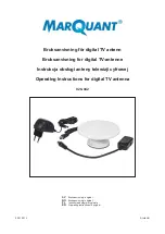
ADJUSTING FOR DIFFERENT CABLE LENGTHS
FIGURE 4
The longer the coaxial cable connecting the UA830 unit and
the receiver or distribution amplifier, the greater the possibility for
signal loss. The UA830 comes with a GAIN switch that can
compensate for signal loss in longer cables. Shure recom-
mends using the Shure UA825 or UA850 coaxial cable when
remote mounting antennas. NOTE: Use only 50
Ω
low-loss
cables (RG-8 or equivalent).
Set the switch according to these guidelines:
"
UA825 Extension Cable (7.6 m [25 ft])—Set GAIN switch
in 3 dB position.
"
UA850 Extension Cable (15.2 m [50 ft])—Set GAIN switch
in 10 dB position.
"
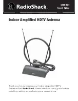
If over 15.2 m (50 ft) is required, a maximum of two
UA830’s may be chained together. Simply connect
coaxial cable from the U4 or UA840 to the TO RECEIVER
port of the first UA830, then run another coaxial cable from
the TO ANTENNA port of the first UA830 to the TO
RECEIVER port of the second UA830. Connect the
antenna to the TO ANTENNA port of the second UA830.
See Figure 5. The Gain switches for each UA830 must be
adjusted separately. No more than two may be chained.
TO ANTENNA
INPUT
TO ANTENNA
TO RECEIVER
TO ANTENNA
TO RECEIVER
CHAINING TWO UA830’S
FIGURE 5
*To maintain Shure UA825 and UA850 cables in top condition in
permanent installations:
1.
Avoid sharp bends or kinks in the cables.
2.
Do not deform cables with makeshift clamps, such as bending
a nail over the cable.
3.
Do not use cables in permanent outdoor installations
4.
Do not expose cables to extreme moisture
SPECIFICATIONS
RF Frequency Range
UA830A
782–810 MHz
. . . . . . . . . . . . . . . . . . . . . . .
UA830B
854–862 MHz
. . . . . . . . . . . . . . . . . . . . . . .
UA830C
800–830 MHz
. . . . . . . . . . . . . . . . . . . . . . .
UA830D
774–782 MHz
. . . . . . . . . . . . . . . . . . . . . . .
Power Consumption (12 Vdc)
1.0 W
±
0.3 W
Signal Gain
Gain switch at 3 dB: 3.5 dB
±
2.0 dB
Gain switch at 10 dB: 10
±
2.0 dB
Input/Output VSWR
Less than 2.0:1
Third Order Intercept Point (3 OIP)
More than 30 dBm
Connectors
Female, BNC-type
Dimensions (without accessories)
66.7 mm high x 31.75 mm wide x 112 mm deep (2.625
x 1.250 x 4.40 inches), 108 mm (4.25 in.) high
w/mounting stand
Case
Aluminum die-casting, black painted
Swivel Adapter
Positive-action, break-resistant, adjustable from 0
°
to
90
°
, with standard
5
/
8
in.-27 thread
Net Weight (without cable)
Without mounting stand: 0.28 kg (9.8 oz)
With mounting stand: 0.42 kg (14.8 oz)
OPTIONAL ACCESSORIES
1/2-Wave Antenna
UA820A
. . . . . . . . . . . . . . . . . . . . . . .
Antenna Distribution System
UA840*
. . . . . . . . . . . . . . . . .
7.6 m (25 ft) Antenna Extension Cable
UA825
. . . . . . . . .
15.2 m (50 ft) Antenna Extension Cable
UA850
. . . . . . . .
* Request compatible frequency range
REPLACEMENT PARTS
Mounting Base
A13HDB
. . . . . . . . . . . . . . . . . . . . . . . . . .
For additional service or parts information, please contact
Shure’s Service department at 1-800-516-2525. Outside the
United States, please contact your authorized Shure Service
Center.
CERTIFICATION
UA830: Eligible for CE Marking; EMC Approved under
ETS 300 445
6
7
www.audiovias.com