background image

17

Digital Feedback Reduction (DFR)

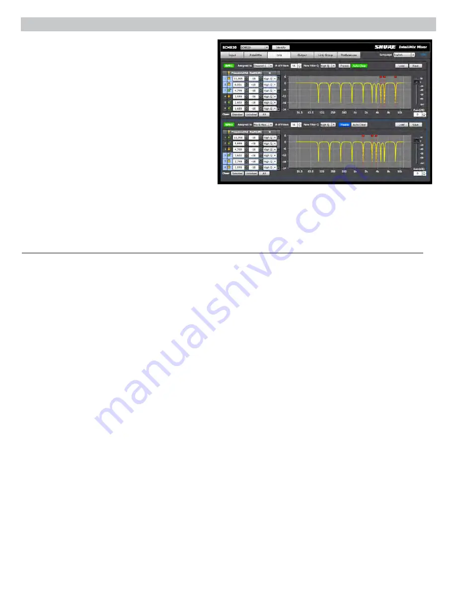
DFR uses Shure’s patented Adaptive Notch Filter algorithm to 

discriminate between feedback and non-feedback sounds. It 

automatically detects feedback and deploys narrow-band notch filters 

at the feedback frequencies. DFR filters are narrow enough to prevent 

any coloration of the audio program. 
No sound system (the combination of microphones, mixing, signal 

processing, power amplifiers, loudspeakers and room acoustics) 

produces an absolutely flat response. When the level of a sound 

system is increased, the frequencies at which peaks occur will be the 

first to exceed the threshold of feedback. The DFR attenuates these 

frequencies, flattening the response of the sound system and enabling 

operation at a higher overall level. 

Function

Use DFR as the initial processor on any channel that receives signal 

from a live microphone where feedback is problematic. When DFR 

detects feedback, it inserts a shallow, narrow filter into the audio 

path to reduce gain at the feedback frequency. This filter is called a 

notch filter, due to the narrow section of the frequency spectrum it 

affects. The notch automatically deepens if feedback continues on that 

frequency.

Basic DFR Setup

Digital Feedback Reducer will not enable you to increase system gain 

beyond the physical limits of the sound system. In most cases, you reach 

a point of diminishing returns after five to eight notch filters are set. This 

is because there are usually only a few dominant peaks in the response 

of the system. In most cases, you can expect a 6 dB to 9 dB improvement 

in gain-before-feedback by using the DFR. When you are ringing out the 

system and notice that many frequencies feedback simultaneously, you 

have reached the point of diminishing returns. If at this point the system still 

has insufficient gain before feedback, other changes must be made to the 

sound system, such as changing the placement of the microphones and/or 

loudspeakers.
There are two basic ways in which to set-up the DFR to reduce feedback; 

the Ring-Out Method and the Insurance Policy Method:

• Ring Out Method - With this method, you use the DFR as a preemptive 

measure against feedback for input channels that operate near the 

feedback point and need an extra margin of stability. Using this 

method, you raise the channel’s gain beyond its normal setting to 

deliberately make the system feed back. The DFR will then set the 

proper filters. Then, when you reduce the input gain to an appropriate 

level, the system is stable and usable.

• Insurance Policy Method - With this method, you use the DFR as 

added insurance against unexpected feedback in an otherwise stable 

system. Simply place the DFR processor in the signal path, without 

defining any settings. This method is used for systems which already 

have sufficient gain-before-feedback, but need protection from 

occasional feedback occurrences due to non-stationary microphones or 

user-adjustable gain controls.

To ring out the system:

1. Remove any active filters by clicking the Clear All button.
2. Place microphones at their intended locations.
3. Set the mixer to Manual to open all mics.
4. Slowly raise the gain of the sound system while talking or clapping into 

the microphones.

5. Assign the DFR to the channel that begins to feed back. If multiple 

microphones feed back in the same frequency, assign the DFR to the 

mix bus.

6. The DFR processor will deploy notch filters to attenuate the feedback 

frequencies.

7. Once the system has stopped feeding back, you can continue by further 

raising the level and repeating the process for additional frequencies. 

Typically you can raise the gain 3 dB to 9 dB above the level at which 

feedback first occurred.

8. Lock the deployed filters so they are fixed. The remaining Unlocked 

(Dynamic) filters will deploy as needed when the system is in use.

Note: Depending on the setup of the sounds system, the main PA signal 

may be separate from the monitor mix signal. Each feedback path should 

include a DFR for the maximum gain before feedback.

Summary of Contents for IntelliMix SCM820-DAN-DB25

Page 1: ...USER GUIDE 27A20290 Rev 4 2017 Shure Incorporated SCM820 Digital IntelliMix Automatic Mixer...

Page 2: ...o Deixe dist ncias suficientes para ventila o adequada e instale de acordo com as instru es do fabricante 8 N O instale pr ximo de nenhuma fonte de calor tais como fogo aceso radiadores bocais de aqu...

Page 3: ...de 11 Single or Dual Mixer Operation 11 Networking 12 Network Overview 12 Digital Audio Networking 12 Dante Software by Audinate 14 Dante Controller 14 Dante Virtual Soundcard 14 Application Examples...

Page 4: ...ambient sound levels Smooth Smooth mode dynamically balances system gain between open and closed channels The system gain remains consistent by distributing gain across channels to equal one open cha...

Page 5: ...Mix B or both for adjustment with the master knob and monitoring on the LED ring and headphone output Note When both Mix A and Mix B are selected the headphone output only monitors Mix A Mix Status In...

Page 6: ...nal path See Configuring the Inputs and Outputs for details on direct output routing Chassis Ground Screw 1 8 Provides an optional connection for microphone shield wire to chassis ground IntelliMix Se...

Page 7: ...B 9 18 24 36 48 60 0 gain limiter L R SUM gain low cut hi shelf meter push to solo hold to mute 1 2 3 4 5 6 7 8 A B HEADPHONE IntelliMix SCM820 AUX IN MASTER lockout power ethernet network audio autom...

Page 8: ...i i i i i i i i i i i gain low cut hi shelf ch meter iiii i i i i i i i i i i i i i i i i gain low cut hi shelf ch meter iiii i i i i i i i i i i i i i i i i iiii i i i i i i i i i i i i i i i i 320 H...

Page 9: ...lockout power ethernet network audio automix link dual mixer LIM A B 9 18 24 36 48 60 0 gain limiter L R SUM gain low cut hi shelf meter push to solo hold to mute 1 2 3 4 5 6 7 8 A B HEADPHONE Intell...

Page 10: ...ix link dual mixer LIM A B 9 18 24 36 48 60 0 gain limiter L R SUM gain low cut hi shelf meter push to solo hold to mute 1 2 3 4 5 6 7 8 A B HEADPHONE 4 5 OUT L R mix a mix b AUX IN 7 gate IN mute ovr...

Page 11: ...t the signal by 12 dB at 5 kHz with a slop of 12dB octave Direct and Mix Outputs Assign the Direct Outputs GUI Only Assign the Direct Output for each channel from the Output tab of the GUI Pre EQ Afte...

Page 12: ...ssic Shure SCM810 automixer in its default settings It is renowned for fast acting seamless channel gating and consistent perceived ambient sound levels The Classic mode excels in most applications sp...

Page 13: ...er operation by pressing the Dual Mixer button on the back panel or from GUI IntelliMix Tab Example Dual Mixer Applications Set Mix A to Classic mode for sound reinforcement and set Mix B to Smooth fo...

Page 14: ...rements To network SCM820 mixers ensure the setup meets the following requirements Use shielded Cat5e cables or higher Cable runs limited to 100 m 328 ft Devices are on the same subnet Dante Network I...

Page 15: ...60 0 gain limiter L R SUM gain low cut hi shelf meter push to solo hold to mute 1 2 3 4 5 6 7 8 A B HEADPHONE IntelliMix SCM820 AUX IN MASTER lockout power ethernet network audio automix link dual mi...

Page 16: ...bit equipment is strongly recommended for Dante network If this is not possible configure the 100 Mbps network with the following guidelines Ensure the router has QoS enabled Latency settings are set...

Page 17: ...channels appear at the mixer s Mix Outputs Aux Channel The aux channel can be set to Local or Global from GUI Inputs Tab Local Aux keeps the Aux signal from appearing on the mix output of other networ...

Page 18: ...the chairperson s microphone activates all other microphones mute automatically Remote Channel Open Indicators Remote indicators can be used to indicate when a talker s microphone is on Connect the LE...

Page 19: ...lacement of the microphones and or loudspeakers There are two basic ways in which to set up the DFR to reduce feedback the Ring Out Method and the Insurance Policy Method Ring Out Method With this met...

Page 20: ...d held microphones In this situation feedback frequencies change drastically as the microphone user wanders the room or sound stage Both fixed and dynamic filters will automatically deepen as addition...

Page 21: ...settings set the device password assign metering type and engage hardware lockout 2 Device List Displays the name of the mixer as set in the Preferences tab Click the drop down bar and select a device...

Page 22: ...two indicators illuminate green when the channel is open to that mix bus Mix A or Mix B When set to Dual Mixer the A and B indicators function separately for each mix 9 Clip Indicator Illuminates when...

Page 23: ...Tab 6 Routing Routes the channel to the Mix A or Mix B output The routing options depend on the Mixer Type Single Mixer Type the channel can route to both or neither mixes Dual Mixer Type the channel...

Page 24: ...enuation Last Mic Lock On and NOMA are disabled in this setting 18 Off Attenuation Sets the amount of attenuation applied to closed channels This is disabled when the Gain Scaling is set to Adaptive 1...

Page 25: ...lect High Q default or Low Q from the drop down menu High Q 1 70th octave Q 101 Low Q 1 40 octave Q 58 10 New Filter Q This selection designates the width of each new filter as it is deployed by DFR 1...

Page 26: ...70 octave or 100 99Q to very wide 4 octaves or 0 27 Q Gain Sets boost or cut of the EQ setting from 18 to 18 dB 8 DFR Enable Disable Button When DFR is assigned from the DFR tab an enable disable butt...

Page 27: ...Auto Link enabled When a device is placed in a group it will automatically configure the unit to the group s settings 3 Stand Alone Devices List Displays all mixers that function independently of a l...

Page 28: ...telliMix Metering Changes the GUI Input meters to display IntelliMix attenuation applied in realtime as displayed with an orange meter Channels that gate open will display more gain than channels that...

Page 29: ...rm 3 Select Apply to set the password Once a password is set any user can log on as a Guest to view the GUI without changing settings To clear a password and allow anyone full editing rights 1 Log on...

Page 30: ...he GUI 4 Language Sets the language of the GUI This setting is saved to the computer s cookies Event Log The event log provides a detailed account of mixer activity from the moment the mixer is powere...

Page 31: ...et the router to not send default gateway as a part of DHCP Manually set the computer to a static IP address on the same network as the mixer GUI is slow Indicators are moving slowly or not displaying...

Page 32: ...ror Code 1 2 3 4 5 6 7 8 Front Panel Error Messages An error message is generated on the Channel LED rings when operating or environmental conditions occur that could potentially harm the mixer These...

Page 33: ...utput Level Impedance Balanced 150 20 dBV Headphone Output 6 35 mm 1 4 TRS 100 mW 350 dual mono will drive stereo phones Digital Signal Processing AD DA Converter 24 bit 48 kHz 113 dB dynamic range ty...

Page 34: ...n 5353 udp mDNS Required for device discovery Open 5568 udp SDT Required for inter device communication Open 8023 tcp Telnet Debug console interface Password 8180 tcp Flash Required for web GUI Open 8...

Page 35: ...tom dual mixer 0dB mic 30dB mic phm 48 VDC CH 46dB reset CHANNEL INTELLIMIX B CC B 0E DD AA 00 auto link gate IN Aux Out mute ovrd gnd L R L 1 14 25 13 R GATE OUT LOGIC GROUND MUTE IN OR OVERRIDE IN 1...

Page 36: ......

Reviews: