SETUP
ÁÁ
ÁÁ
ÁÁ
ÁÁ
Á
Á
Á
Á
Á
Á
Á
Á
Á
ÁÁ
Á
Á
Á
Á
Á
Á
Á
Á
Á
Á
Á
Á
Á
ÁÁ
Á
Á
Á
Á
Á
Á
ÁÁÁ
ÁÁÁ
ÁÁÁ
ÁÁÁ
Á
Á
ÁÁ
Á
ÁÁÁÁ
ÁÁÁÁ
Á
ÁÁÁÁ
ÁÁÁÁ
Á
Á
Á
ÁÁÁÁ
ÁÁÁÁ
ÁÁÁÁ
Á
Á
Á
Á
Á
ÁÁÁÁ
Á
Á
Á
Á
ÁÁÁÁ
Á
Á
Á
Á
Á
Á
Á
Á
Á
Á
Á
Á
Á
Á
Á
Á
Á
Á
Á
Á
Á
Á
Á
Á
Á
Á
Á
Á
Á
Á
Á
Á
Á
Á
Á
Á
Á
Á
Á
Á
Á
Á
Á
Á
Á
Á
ÁÁ
ÁÁ
Á
Á
Á
ÁÁ
ÁÁ
Á
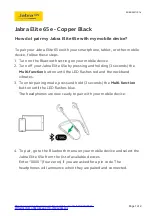
Receiver
Transmitter
Headset
Computer
SETUP OVERVIEW
FIGURE 3
RECEIVER SETUP (SEE FIGURE 4)
1.
Affix the four adhesive rubber feet or the VELCRO fastening strips to the
bottom of the receiver and mount it on a flat surface.
NOTE: It is best not to place the receiver directly next to or on top of your
computer, monitor, or other electronic equipment, as these type of devices
can generate rf interference.
2.
Plug the supplied ac power adapter (PS20 or PS20E) into a wall socket
or other electrical outlet.
3.
Connect the ac adapter cable to the receiver DC INPUT connector. The
green POWER light on the receiver should come on.
4.
Connect the receiver ’s AUDIO OUT to the MIC input on your computer
or sound card using the supplied audio cable.
5.
Fully extend the telescoping antenna and adjust it so that it is vertical.
Á
Á
Á
ÁÁ
ÁÁ
Á
Á
ÁÁ
ÁÁ
Á
Á
Á
Á
Á
Á
Á
Á
Á
Á
Á
Á
Á
Á
Á
Á
Á
Á
Á
Á
Á
Á
Á
Á
Á
Á
Á
Á
Á
Á
Á
ÁÁ
Á
Á
Á
Á
ÁÁ
Á
Á
ÁÁ
Á
Á
Á
Á
Á
Á
ÁÁ
Á
Á
Á
Á
Á
Á
Á
Á
Á
Á
Á
ÁÁÁÁÁÁ
ÁÁÁÁÁÁ
ÁÁÁÁÁ
ÁÁÁÁÁ
ÁÁÁÁÁ
ÁÁÁÁÁ
ÁÁÁÁÁÁ
Á
ÁÁ
Á
Á
Á
Á
Á
Á
Á
Á
Á
Á
Á
Á
ÁÁ
Á
Á
ÁÁ
ÁÁ
Á
ÁÁ
ÁÁ
Á
ÁÁ
Á
Á
Á
ÁÁ
ÁÁ
MIC Input
90
°
AUDIO OUT
Computer
Receiver
TRANSMITTER SETUP
FIGURE 4
TRANSMITTER SETUP
1.
Install the supplied 9 V alkaline battery.
a) Turn off the transmitter.
b) Press down on the OPEN side of the battery compartment cover, slide
it back and flip it open, as shown in Figure 5.
c)
Insert the supplied 9 V alkaline battery into the battery compartment
as shown in Figure 5. Make sure the “+” and “–” battery terminals
match the “+” and “–” terminals on the transmitter.
NOTE: A Duracell MN1604 battery, like the one supplied, is recommended.
A fresh 9 V alkaline battery should typically provide 18 hours of perfor-
mance time. A fully charged 8.4 V NiCad rechargeable battery should pro-
vide 2 hours of performance time. When the red LOW BATTERY light on
the transmitter glows, you have 1 hour or less of useful battery life remain-
ing.
IMPORTANT: Carbon-zinc and zinc-chloride batteries will not provide ad-
equate power and are not recommended.
Á
Á
Á
Á
Á
Á
Á
Á
Á
Á
Á
Á
Á
Á
Á
Á
Á
Á
Á
ÁÁÁ
Á
Á
Á
Á
Á
Á
Á
Á
ÁÁÁ
Á
Á
Á
Á
Á
Á
Á
Á
Á
Á
Á
Á
Á
Á
Á
Á
Á
Á
ÁÁÁ
Á
Á
Á
Á
Á
Á
Á
Á
ÁÁÁ
Á
Á
Á
Á
Á
Á
Á
Á
Á
Á
Á
Á
Á
Á
Á
Á
Á
Á
Á
Á
Á
Á
Á
Á
Á
Á
ÁÁÁ
Á
Á
Á
Á
TC1 BATTERY INSTALLATION
FIGURE 5
2.
Attach the transmitter belt clip to your belt so that the antenna hangs
downward and is not coiled or bundled.
ÁÁÁ
Á
Á
Á
Á
Á
Á
Á
Á
Á
Á
ÁÁ
ÁÁ
ÁÁ
Á
Á
Á
ÁÁ
ÁÁ
Á
Á
Á
Á
Á
Á
ÁÁ
ÁÁ
Á
Á
Á
Á
ÁÁ
ÁÁ
Á
ÁÁ
ÁÁ
Á
Á
Á
Á
Á
Á
Á
Á
Á
Á
Á
Á
Á
ÁÁÁ
Á
Á
Á
Á
Á
Á
Á
Á
ÁÁ
ÁÁÁÁ
ÁÁÁÁ
ÁÁÁÁ
ÁÁÁÁ
Á
Á
ÁÁÁÁ
ÁÁ
ÁÁ
ÁÁ
Á
ÁÁÁÁ
ÁÁÁ
ÁÁÁÁÁ
ÁÁÁÁÁ
ÁÁÁ
ÁÁÁ
ÁÁ
ÁÁ
ÁÁÁ
ÁÁÁ
ÁÁÁ
ÁÁÁ
ÁÁÁ
ÁÁÁ
ÁÁÁ
ÁÁÁ
ÁÁÁÁ
ÁÁÁÁ
ÁÁÁÁ
ÁÁÁÁ
ÁÁÁÁ
ÁÁÁÁ
ÁÁÁÁ
ÁÁÁÁ
ÁÁÁÁ
Á
Á
Á
USING THE BELT CLIP
FIGURE 6
3.
Slide the transmitter power switch to the ON position. The green POWER
ON light on the transmitter should illuminate, indicating that the transmitter
is working properly.
NOTE: When not in use, turn the transmitter power off to conserve battery
power.
4
5