

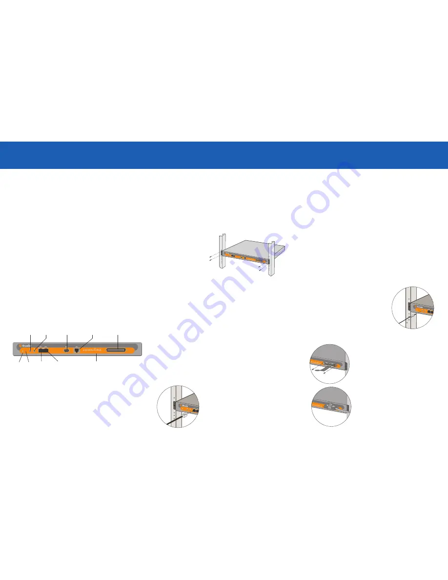
ShoreGear-
60/12
Power
LED
LAN 2
connector
Analog port LEDs
LAN 1
connector
Audio input port
(music-on-hold)
RS-232C
maintenance
port
RJ-11
Power Fail Transfer
port
RJ-21X
Telco port
Audio output port
(night bell)
Choosing a Location
To ensure optimum operating conditions for the ShoreGear voice switch, make
sure that its operating environment is adequately ventilated, free of gas or airborne
particles, and isolated from electrical noise.
Installing the ShoreGear Voice Switch (Rack Mount)
The ShoreGear voice switch is equipped with pre-installed rack-mount ears for easy
installation into a standard 19-inch rack.
Introduction
About the ShoreGear-60/12
The ShoreGear-60/12 Voice Switch connects enterprise telephone extensions
through an internal IP network, or to any central office (CO) analog trunk line.
The switch provides connectivity through:
• Two RJ-45 local area network (LAN) connectors
• One RJ-21X port for connecting the switch to a telephone company punch-
down block, patch panel, or 12-port harmonica connector.
• One RJ-11 port for connection to the extension side of the Power Fail Transfer
Unit (Extension 9)
• One DB-9, RS-232C maintenance port (19200 bps, 8 bits, no parity, 1 stop bit,
no handshake) for serial communications
• One audio input port (3.5 mm stereo) for connecting a music-on-hold source
• One audio output port (3.5 mm stereo) for connecting the switch to a corporate
paging system or night bell
The ShoreGear-60/12 Voice Switch package contains:
• ShoreGear-60/12 Voice Switch
• Power cord
• Stick-on feet
(for surface installation)
• ShoreGear-60/12 Telco cable
• Cable retainer for the ShoreGear-60/12 Telco cable
(a metal bracket with a Velcro strap)
Installation
1
Lift the ShoreGear voice switch
to the desired height and
attach it to the frame with four
standard rack screws.
2
Insert the screws in both the
upper and lower positions on
the rack-mount ears.
ShoreGear
™
60/12
What You Need for Installation
To install the switch, you need the following equipment:
• AC surge protector for the power connection
• RJ-45 cable for connecting the switch to the local area network
• Music-on-hold source with a standard mini-headphone Y-adapter (optional)
• Permanent earthing connector for grounding the device
• RJ-21 telephone cable for telephone- and trunk-line connections (optional)
• RJ-21 to RJ-11 patch panel for connecting telephones and trunk lines
• #1 Phillips screwdriver
Connections
ShoreGear
™
60/12
ShoreGear
™
60/12
NOTE
:
Make sure there is at least
two inches of open space around all vent holes.
Mounting the ShoreGear Voice Switch on a Flat Surface
If you plan to mount the switch on a flat surface, first attach the provided rubber feet
to the bottom corners of the device. (You can stack up to three switches in a surface
installation.)
Attaching an Earthing Connector
To meet UL requirments for proper grounding, you must connect a permanent
earthing protector between the ShoreGear voice switch and the wiring system
ground.
1
Connect a ground wire (#16 AWG wire or larger) to the screw on the back of the
unit and to the right of the product label.
2
Connect the other end of the ground wire to the wiring system ground.
CAUTION:
Always connect the permanent earthing connector before attempting to
connect the switch to a LAN segment and telecommunication lines.
Connecting the ShoreGear Voice Switch to the Network
Once the ShoreGear-60/12 Voice Switch is secured to a rack or surface-mounted, you
can connect it to the data network.
Powering on the ShoreGear Voice Switch
After connecting the switch to the network, power on the device by connecting it to
an AC power source.
1
Plug an AC surge protector (not provided) into a grounded AC power source.
2
Plug one end of the provided power cord into the receptacle on the back of the
switch, then plug the other end into the AC surge protector.
The power LED flashes momentarily, and remains lit.
• If the LED is not lit, make sure the power cord is plugged into the switch and the
power source.
• If the LED continues flashing, there is an internal error. Unplug the switch to
power it off, then power it back on. Refer to the “Configuring Switches” chapter
in the
ShoreTel Administration Guide
for information on flash patterns, or contact
the ShoreTel Customer Response Center at http://www.shoretel.com.
The LAN ports auto-sense the network transport rate. When the network
connection is established, the network LED indicates a transport rate of 10 Mbps or
100 Mbps, and whether the switch is receiving and transmitting data.
Optional Connections
After connecting the voice switch to the LAN, you can make optional connections,
including input from a music-on-hold source or output to
your internal paging system.
•
Use an RJ-45 Ethernet cable to connect one or both
of the LAN ports to the network subnet.
NOTE:
While both ports can detect and respond to link
status, the switch uses only one LAN port at a time.
1
Connect a music-on-hold source (CD player or
other audio source) to the audio input port.
2
Connect your site’s paging system to the audio
output port.
Connecting Trunk and Telephone Lines
Use the provided ShoreGear-60/12 Telco cable and cable retainer to connect the
voice switch to the telephone company’s punch-down block or patch panel.
1
Use a #1 Phillips screwdriver to remove the
two screws on either side of the RJ-21X port,
then place the retainer on the port and re-
attach the screws.
2
Plug the Telco cable into the port, then pull
the Velcro strap tightly around the cable
connector and fasten it.
3
Connect the other end of the Telco cable to
the punch-down block or patch panel.
CAUTION:
To reduce risk of fire, always use #26
AWG or larger telecommunications line cable.
NOTE
: For detailed information on switch
port and trunk configuration, see the sections
“Configuring Switches” and “Configuring Trunks”
in the
ShoreTel Administration Guide.
Default
switch


