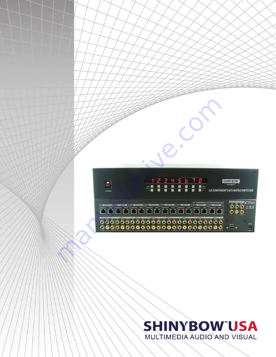
SB-5588CT
8x8 HDTV Component Video w/ Digital and Stereo Audio
Matrix Routing Switch w/ CAT5 Output
INSTRUCTION MANUAL
Page 1: ...SB 5588CT 8x8 HDTV Component Video w Digital and Stereo Audio Matrix Routing Switch w CAT5 Output INSTRUCTION MANUAL ...
Page 2: ...ion 12 This unit should be installed in a cool dry place away from sources of excessive heat vibration dust moisture and cold Do not use the unit near stoves heat registers radiators or other heat producing devices 13 Do not block fan intake or exhaust ports Do not operate equipment on a surface or in an environment which may impede the normal flow of air around the unit such as a bed rug carpet o...
Page 3: ...ghly reliable but it is essential that you read this manual thoroughly before attempting to use the 8x8 Component Video Digital Stereo Audio Over CAT5 Matrix Switcher TABLE OF CONTENTS SAFETY PRECAUTIONS Please read all instructions before attempting to unpack install or operate this equipment and before connecting the power supply Please keep the following in mind as you unpack and install this e...
Page 4: ...t Video YPBPR 0 5 1 0Vpp DDC 5Vpp 1x Digital Audio PCM via 1x RCA connector 1x Stereo Audio AR AL via 2x RCA connector Red white Output Ports A Group 1x CAT5 Component Video YPBPR 0 5 1 0Vpp DDC 5Vpp via 1x RJ 45 CAT5 connector 1x CAT5 Digital Audio PCM and Stereo Audio AR AL via 1x RJ 45 CAT5 connector Video Bandwidth 325MHz 3db 200mVp p Video Supported Higher resolution formats 480i p 720p 1080i...
Page 5: ...iate switch the power switch to ON and you should see and hear the signals on the devices you have connected to the various output connectors of the SB 5588CT POWER AND CONNECTIONS This unit is not disconnected from the AC power source as long as it is connected to the wall outlet The off state for this unit is called standby mode In standby mode the unit is designed to consume a reduced quantity ...
Page 6: ...Input 1 8 port source signals Component Video YPBPR 3x RCA Connectors Digital Audio PCM 1x RCA Connector Stereo Audio AR AL 2x RCA Connectors 5 OUTPUTS 1 8COMPONENT DIGITAL AUDIO Connects a Component Video YPBPR Digital Audio PCM Stereo Audio signal source device to the 8x8 switcher Output 1 8 display port signals Component Video YPBPR 3x RCA Connectors Digital Audio PCM 1x RCA Connector Stereo Au...
Page 7: ...dio visual sources For each destination output select the appropriate input source by using the front panel input 1 8 select buttons The supplied IR remote control Or through the RS 232 serial communications port Upon power up the switcher will return to its last used setting before Powered down REMOTE CONTROL 1 2 SWITCH POWER ON or OFF Controller with a power ON and OFF 3 INPUT 1 8 TV VIDEO DISPL...
Page 8: ... 2 02FD 12ED INPUT 2 OUTPUT 3 02FD 13EC INPUT 2 OUTPUT 4 02FD 14EB INPUT 2 OUTPUT 5 02FD 15EA INPUT 2 OUTPUT 6 02FD 16E9 INPUT 2 OUTPUT 7 02FD 17E8 INPUT 2 OUTPUT 8 02FD 18E7 INPUT 3 OUTPUT 1 03FC 11EE INPUT 3 OUTPUT 2 03FC 12ED INPUT 3 OUTPUT 3 03FC 13EC INPUT 3 OUTPUT 4 03FC 14EB INPUT 3 OUTPUT 5 03FC 15EA INPUT 3 OUTPUT 6 03FC 16E9 INPUT 3 OUTPUT 7 03FC 17E8 INPUT 3 OUTPUT 8 03FC 18E7 INPUT 4 O...
Page 9: ...value is changed from the front panel or by IR control If the unit needs to be controlled via the front panel in addition to the RS 232 control you should regularly poll the unit status to ensure the control system accurately reflects the current settings PROTOCOL COMMANDS To Switch Inputs to Outputs SBI0XO0Y Where X is Output Number 1 8 and Y is Number 1 8 Unit will respond with SBUD0XOY Where X ...
Page 10: ...sent while in Power Off state A hard reset command SBALLRST will return the unit to normal operation and also unlock the front panel Power Off mode SBSYSMOF Put system into Standby Soft Power Off SBSYSMON Bring unit out of Standby Soft Power On Unit will respond with SBALOFAK Unit is in Standby SBALONAK Unit is no longer in Standby Example Put Unit in Standby Soft Power SBSYSMOF Send SBALOFAK Rcvd...
Page 11: ... 100C IR Receiver Cable Signal center GND Sleeve Tip Ring Sleeve Tip Signal Ring NC Sleeve GND Ring Tip center Sleeve The SB 100 IR Receiver is required when using the port ALL in Jack The SB 100C IR Receiver will not function on the port ALL in Jack SB 100C Maximum Distance 6 feet 2M INP UT DC 12V RoHS 95 EC IR EXT RS 232 R S 232 IR E XT in ANI 100 IR Rx P O W E R IN P U T 1 1 2 3 4 1 2 3 4 1 2 3...
Page 12: ...101 IR Transmitter Set Note The External IR jack has voltage on the Ring portion of a 3 conductor plug You must use a 3 conductor plug aka stereo plug Using a 2 conductor plug will short out the power supply Always make connections with the switcher power off When you plug the External IR extender into the switcher the front panel IR transmitter remains active IR Transmitter cable 6ft 2M SB 101C T...
Page 13: ...nt Video YPBPR connector with RCA DIGITAL Digital Audio PCB connector with RCA AUDIO Stereo Audio AR AL connector with RCA OUTPUT 1 8 PORT CAT5 CONNECT TO DISPLAY SIGNALS CAT5 1 Component Video YPBPR connector with RJ 45 CAT5 2 Digital Audio PCB Stereo Audio AR AL connector with RJ 45 SB 5588CT SUPPORTS 8 COMPONENT INPUTS MATRIX TO 8 SWITCH OUTPUTS SUPPORTS CONTROL IR RS 232 INTERFACE SYSTEM PORTS...
Page 14: ...s United States ofAmerica SHINYBOWUSA makes no representation that materials pertaining to the Product are appropriate or available for use in other locations other than the shipping address you provided with respect thereto You are advised that the Product may be subject to U S export controls DISCLAIMERS AND LIMITATION OF LIABILITY SHINYBOWUSA may change or modify the Product at any time from ti...
Page 15: ...THIS PAGE IS INTENTIONALLY LEFT BLANK ...
Page 16: ...122 Rose Ln Suite 303 Frisco Texas 75034 1 877 SHINY USA 1 877 744 6987 1 972 377 2508 sales shinybowusa com www shinybowusa com ...