background image

Appendix

-95

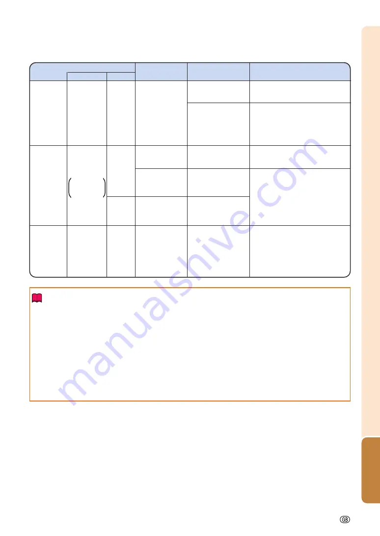
Maintenance indicator

Problem

Cause

Possible solution

Temperature

warning

indicator

Normal

Abnormal

Off

Red on

(Standby)

The internal
temperature is
abnormally high.

Abnormal

 Blocked air intake

Relocate the projector to an area
with proper ventilation. (See page

9

.)

Cooling fan break-
down

Internal circuit failure

Clogged air intake

Clogged intake vent
cover

Take the projector to your nearest
Sharp Authorized Projector Dealer
or Service Center for repair. (See
page 

104

.)

Clean the air vents and the intake
vent cover. (See page 

93

.)

Lamp

indicators

1, 2

Red on

(Standby)

The lamp does
not illuminate.

Burnt-out lamp

Lamp circuit failure

Carefully replace the lamp. (See
page 

97

.)

Take the projector to your nearest
Sharp Authorized Projector Dealer
or Service Center for repair. (See
page 

104

.)

Please exercise care when
replacing the lamp.

Red on

Time to change
the lamp.

Remaining lamp life
becomes 5% or less.

Green on

Green blinks

when the lamp

is warming up.

Info

If the temperature warning indicator blinks and the projector enters the standby mode, the temperature
warning indicator starts to illuminate. Check whether any of the ventilation holes are blocked (see page 

10

)

and then try turning the power back on. Wait until the projector has cooled down completely before plugging
in the power cord and turning the power back on. (At least 10 minutes.)

If the power is turned off for a brief moment due to power outage or some other cause while using the
projector, and the power supply recovers immediately after that, the lamp indicator will illuminate in red
and the lamp may not be lit. In this case, unplug the power cord from the AC outlet, replace the power
cord in the AC outlet and then turn the power on again.

The cooling fan keeps the internal temperature of the projector constant and this function is controlled
automatically. The sound of the cooling fan may change during operation because the fan speed may
change and this is not a malfunction.

The lamp does
not illuminate.

The lamp is shut
down abnormally.

Disconnect the power cord from
the AC outlet, and then connect it
again.

Power

indicator

Green on/

Red on

Red
blinks

The power
indicator blinks in
red when the
projector is on.

•••••

The intake vent
cover is open.

•••••

Securely install the cover.

•••••

If the power indicator blinks even
when the intake vent cover is
securely installed, contact your
nearest Sharp Authorized Projector
Dealer or Service Center for
advice. (See page 

104

.)

Summary of Contents for XG-PH70X - XGA DLP Projector

Page 1: ...MODEL XG PH70X Standard zoom lens attached XG PH70X N No lens attached MULTIMEDIA PROJECTOR OPERATION MANUAL Introduction Quick Start Setup Connections Basic Operation Useful Features Appendix ...

Page 2: ...ked with the letter N or coloured black The wire which is coloured brown must be connected to the terminal which is marked with the letter L or coloured red IF YOU HAVE ANY DOUBT CONSULT A QUALIFIED ELECTRICIAN The supplied CD ROM contains operation instructions in English German French Swedish Spanish Italian Dutch Portu guese Chinese Korean and Japanese Carefully read through the operation instr...

Page 3: ...le is intended to alert the user to the presence of uninsulated dangerous voltage within the product s enclosure that may be of sufficient magnitude to constitute a risk or electric shock to persons The exclamation point within a triangle is intended to alert the user to the presence of important operating and maintenance servicing instructions in the literature accompanying the product Introducti...

Page 4: ...deo systems and video cameras there are certain acceptable tolerances that the equipment must conform to This unit has some inactive pixels within acceptable tolerances which may result in inactive dots on the picture screen This will not affect the picture quality or the life expectancy of the unit DLP and the DLP logo are registered trademarks of Texas Instruments Microsoft and Windows are regis...

Page 5: ...e lected input mode is displayed 2 Press or to display the other menu items There are eight menu items as shown below Note The Fine Sync menu is not available for selecting INPUT 4 or INPUT 5 Menu item How to Read This Operation Manual In this operation manual the illustrations and on screen displays are simplified for explana tion This may differ from the actual on screen display Info Indicates s...

Page 6: ...d Connectable Main Equipment 24 Samples of Cables for Connection 25 Connecting to a Computer 27 Connecting with the RGB Cable 27 Connecting with a 5 BNC to 15 pin D sub Cable 28 Connecting with a DVI Digital Cable 29 Connecting to Video Equipment 30 Connecting to Video Equipment That Has an HDMI Output Terminal with a DVI to HDMI Cable 30 Connecting to Video Equipment That Has a DVI Output Termina...

Page 7: ...rily 46 Displaying an Enlarged Portion of an Image 46 Freezing a Moving Image 47 Selecting the Picture Mode 47 Resize Mode 48 Displaying the Black Screen 50 Displaying and Setting the Break Timer 50 Turning the Projector On Off 37 Image Projection 38 Shifting the Lens 38 Using the Adjustment Feet 39 Adjusting the Focus 40 Adjusting the Projected Image Size 40 Correcting Trapezoidal Distortion 41 S...

Page 8: ...pendix Maintenance 93 Maintenance Indicators 94 Regarding the Lamp 96 Lamp 96 Caution Concerning the Lamp 96 Replacing the Lamp 96 Removing and Installing the Lamp Unit 97 Resetting the Lamp Timer 99 Computer Compatibility Chart 100 Troubleshooting 102 For SHARP Assistance 104 Specifications 105 Glossary 106 Index 107 ...

Page 9: ...en you want to view the operation manual 1 Double click the MANUALS folder 2 Double click the language name of the folder that you want to view 3 Double click the PH70_ pdf file to access the projector manuals When you want to view the setup manual 1 Double click the SETUP folder 2 Double click the language name of the folder that you want to view 3 Double click the S_PH7_ pdf file to access the s...

Page 10: ...ying particular attention to cords at plugs convenience receptacles and the point where they exit from the product 14 Lightning For added protection for this product during a lightning storm or when it is left unattended and unused for long periods of time unplug it from the wall outlet and disconnect the cable system This will prevent damage to the product due to lightning and power line surges 1...

Page 11: ...wing difficult Close the curtains and dim the lights when setting up the screen in a sunny or bright room The projector may be safely tilted to a maximum angle of 9 degrees Placement should be within 9 degrees of horizontal If you have application requiring tilt angle exceeding 9 degrees please check with your local Sharp sales office When using the projector in high altitude areas such as mountai...

Page 12: ...arest wall or obstruction Ensure that the intake vents and the exhaust vent are not obstructed If the cooling fan becomes obstructed a pro tection circuit will automatically put the pro jector into standby mode to prevent overheat damage This does not indicate a malfunc tion See pages 94 and 95 Remove the pro jector power cord from the wall outlet and wait at least 10 minutes Place the projector w...

Page 13: ...rd zoom lens Only supplied with XG PH70X 9NK3797200400 Supplied accessories RGB cable 10 3 0 m 9NK3080431000 For U K Hong Kong and Singapore 6 1 8 m 9NK3090152900 For Australia New Zealand and Oceania 6 1 8 m 9NK3090152600 Operation manual this manual 9NK5010057700 Remote control 9NK5041808700 Cable 3 RCA to 15 pin D sub cable 10 3 0 m AN C3CP2 Lamp Lamp unit 1 AN PH7LP1 Lamp unit 2 AN PH7LP2 Note...

Page 14: ...st Sharp Authorized Projector Dealer for details on all the lenses Refer to the lens operation manual when using a lens Also be sure to have service personnel install the optional lenses Throw Distance The graph below is for 100 inches 254 cm screen with 4 3 normal mode Screen 5 10 15 20 25 30 35 45 50 40 ft Standard zoom lens AN PH31EZ Standard equipment with XG PH70X 12 14 8 3 7 m 4 5 m Throw di...

Page 15: ...revious display AUTO SYNC button For automatically adjusting images when connected to a computer INPUT 1 2 3 button For switching input mode 1 2 or 3 INPUT 4 5 button For switching input mode 4 or 5 Volume buttons For adjusting the speaker sound level Temperature warning indicator Lamp indicator 2 Lamp indicator 1 Remote control sensor Speaker Adjustment foot on the bottom of the projector 93 Inta...

Page 16: ...t cover is open See page 93 Temperature warning indicator Off Normal Red blinks on The internal temperature is abnormally high See pages 94 and 95 Lamp indicators 1 2 Green on Normal Green blinks The lamp is warming up Red on The lamp has been shut down abnormally or needs to be changed See pages 94 and 95 Part Names and Functions ...

Page 17: ...olling the projector using a computer WIRED REMOTE terminal For connecting the remote control to the projector when the signals from the remote control cannot reach the remote control sensor INPUT 3 terminal Terminal for DVI digital RGB and digital component signals OUTPUT FOR INPUT 1 2 terminal Output terminal for computer RGB and component signals Shared for INPUT 1 and 2 AUDIO input 2 3 termina...

Page 18: ...hile the ADJ MOUSE switch is the MOUSE position For selecting menu items while the ADJ MOUSE switch is the ADJ position ENTER button For setting items selected or adjusted on the menu FREEZE button For freezing images RESIZE button For switching the screen size BLACK SCREEN button For temporarily display the black screen PICTURE MODE button For switching the picture mode WIRED R C JACK For connect...

Page 19: ...leak Battery fluid from leaked batteries is harmful to skin therefore ensure you wipe them first and then remove them using a cloth The batteries included with this projector may run down in a short period depending on how they are kept Be sure to replace them as soon as possible with new batteries Remove the batteries from the remote control if you will not be using the remote control for a long ...

Page 20: ...red the ø3 5 mm minijack cable should be discon nected from the projector Switching the Remote Control Mode The remote control has two functions One is projector control and the other is wireless computer mouse Slide the ADJ MOUSE switch on the remote control to other side compatible to the desired usage Info When using the remote control as the wireless computer mouse connect the supplied remote ...

Page 21: ...your computer supports only a one click mouse such as Macintosh Press or and have com mon function ADJ MOUSE Remote mouse receiver Supplied accessory Note This function only works with the Microsoft Windows OS and Mac OS However this func tion does not work with the following operation systems that do not support USB Versions earlier than Windows 95 Versions earlier than Windows NT4 0 Versions ear...

Page 22: ...or details see the page described below for each step Setup and Projection In this section connection of the projector and the computer is explained using one example 2 Connect the projector to the computer and plug the power cord into the AC socket of the projector 3 Remove the lens cap and turn the projector on When connecting equipment other than the computer see pages 30 36 5 4 6 6 7 6 3 4 8 3...

Page 23: ...d even if the projector is operating Even if you unplug the power cord from the AC outlet the cooling fan continues to run for a while Adjust the projector angle Shift the lens horizontally and vertically 1 1 1 1 1 Press on the projector or on the remote control 2 2 2 2 2 Press or on the projector or the remote control Adjust the projector angle by rotating the adjust ment feet 6 Correcting the im...

Page 24: ... on the screen washes out the colors making viewing difficult Close the curtains and dim the lights when setting up the projector in a sunny or bright room Standard Setup Front Projection Place the projector at the required distance from the screen according to the desired picture size For details refer to SETUP MANUAL contained on the supplied CD ROM Setting Up the Projector Indication of the Pro...

Page 25: ...mirror are carefully placed so the projected light does not shine into the eyes of the audience Ceiling mount Setup It is recommended that you use the optional Sharp ceiling mount bracket for this installation Before mounting the projector contact your nearest Sharp Au thorized Projector Dealer or Service Center to obtain the recom mended ceiling mount bracket sold separately AN PHCM20 ceiling mou...

Page 26: ...BASE TX Connecting the computer or the hub using a LAN cable See page 35 INPUT 5 terminal Connecting video equipment with S video output terminal VCR DVD player etc See page 34 RS 232C terminal Connecting the computer to control the projector See page 35 INPUT 4 terminal Connecting video equipment without S video output terminal See page 34 OUTPUT FOR INPUT 1 2 terminal Connecting the monitor when...

Page 27: ...cially available DVI Digital cable commercially available ø3 5 mm stereo or mono audio cable commercially available or available as Sharp service part QCNWGA038WJPZ DVI to HDMI cable commercially available DVI Digital cable commercially available 5 RCA RGB cable commercially available BNC to RCA adaptors commercially available 3 RCA to 15 pin D sub cable optional AN C3CP2 BNC to RCA adaptors comme...

Page 28: ...terminal S video output terminal Audio output terminal RGB input terminal Audio input terminal Cable Video cable commercially available S video cable commercially available ø3 5 mm stereo minijack to RCA audio cable commercially available RCA audio cable commercially available RGB cable supplied or commercially available ø3 5 mm stereo minijack to RCA audio cable commercially available Samples of ...

Page 29: ... projector the computer or both A Macintosh adaptor may be required for use with some Macintosh computers Contact your nearest Macintosh Dealer Depending on the computer you are using an image may not be projected unless the computer s external output port is switched on e g Press Fn and F5 keys simultaneously when using a SHARP notebook computer Refer to the specific instructions in your computer...

Page 30: ...ible computer other than a PC VGA SVGA XGA SXGA UXGA or Macintosh i e Workstation a separate cable may be needed Please contact your dealer for more information When using the ø3 5 mm mono audio cable the volume level will be half of when using the ø3 5 mm stereo audio cable The HD C sync terminal is only for TTL signal Computer Side view ø3 5 mm stereo or mono audio cable commercially available o...

Page 31: ... D PC RGB for Signal Type in the Picture menu When using the ø3 5 mm mono audio cable the volume level will be half of when using the ø3 5 mm stereo audio cable Computer Side view ø3 5 mm stereo or mono audio cable commercially available or available as Sharp service part QCNWGA038WJPZ To INPUT 3 terminal DVI Digital cable commercially available To DVI digital output terminal To audio output termi...

Page 32: ...ting HDMI video equipment such as DVD players to the INPUT 3 terminal Note Select the input signal type of the video equipment See page 63 While the projector is connected to video equipment that has an HDMI output terminal only the video signal can be input to the projector Connect the AUDIO input 2 3 terminal for audio input Depending on specifications of video equipment or DVI to HDMI digital c...

Page 33: ...he DVI output terminal such as DVD players to the INPUT 3 terminal Note Select the input signal type of the video equipment See page 63 To INPUT 3 terminal DVI Digital cable commercially available To audio output terminals To AUDIO input 2 3 terminal ø3 5 mm stereo minijack to RCA audio cable commercially available To DVI output terminal Video Equipment Side view ...

Page 34: ...ture menu See page 63 The HD C sync and VD terminals may be used depending on the specifications of the DTV decoder connected to this projector Please refer to the operation manual of the DTV decoder for details The HD C sync terminal is only for TTL signal Connecting to Video Equipment Side view To INPUT 2 terminals BNC to RCA adaptors commercially available 5 RCA RGB cable commercially available...

Page 35: ...1 pin RGB output Euro scart to the projector use a com mercially available cable that fits in the projector terminal you want to connect The projector does not support RGBC signals via the Euro scart To audio output terminals ø3 5 mm stereo minijack to RCA audio cable commercially available To component video output terminals To INPUT 1 terminal To AUDIO input 1 terminal 3 RCA to 15 pin D sub cabl...

Page 36: ...commercially available is required for audio input When you connect video equipment with a 21 pin RGB output Euro scart to the projector use a com mercially available cable that fits in the projector terminal you want to connect RCA audio cable commercially available To video output terminal Composite video cable commercially available To INPUT 5 terminal To AUDIO input 4 5 terminals To audio outp...

Page 37: ... than the RS 232C terminal on the computer This may damage your computer or projector Do not connect or disconnect an RS 232C serial control cable to or from the computer while it is on This may damage your computer When connecting to the LAN terminal using a LAN cable Note When connecting to a hub use straight through Category 5 CAT 5 type cable commercially available When connecting to a compute...

Page 38: ... audio cable commercially available is required for audio input When turning off the power in the case of connecting an amplifier or other audio equipment first turn off the power of the amplifier and then turn off the power of the projector By using external audio components the volume can be amplified for better sound For details on Variable Audio Output VAO and Fixed Audio Output FAO see page 7...

Page 39: ...indicator illuminates the projec tor is ready to start operation When System Lock is set the keycode input screen appears Enter the right keycode to start projection See page 79 for details Note The lamp indicator illuminates or blinks in dicating the status of the lamp Green The lamp is on Blinking green The lamp is warming up Red The lamp is shut down abnor mally or the lamp should be replaced W...

Page 40: ...upward or downward When moving in the left and right direction Adjustable range Adjustable range Image center Width of the image 15 Height of the image 50 Height of the image 10 AN PH20EZ AN PH31EZ AN PH40EZ AN PH50EZ AN PH60EZ The position of the image when the vertical position of the image is center and the horizontal position is the lowest Areas on which the image is masked with a shadow while...

Page 41: ...ent feet The projector is adjustable up to approxi mately 9 degrees 2 Lower the projector and then ro tate the adjustment feet for the fine adjustment When lowering the projector be careful not to get your fingers caught in the area between the adjustment feet and the projector Adjustment feet Up Up Down Down ENTER button Adjustment button H V LENS SHIFT button Mouse adjustment button ENTER button...

Page 42: ...FOCUS but tons or the ZOOM buttons the projected image moves a small amount toward the desired direction for approximately one second Hold down the buttons to move the projected image quickly Adjusting the Focus Press on the projector or on the remote control to adjust the fo cus Adjusting the Projected Image Size Press on the projector or on the remote control to adjust the pro jected image size ...

Page 43: ... Selecting the Type of the Correction Select the type of the keystone correction Press on the projector or on the remote control GEOMETRIC ADJUSTMENT will be dis played Each time or is pressed the display toggles as follows GEOMETRIC H V KEYSTONE ADJUSTMENT The display IMAGE RESIZING disappears Correcting Trapezoidal Distortion When the image is projected either from the top or from the bottom tow...

Page 44: ... the projector or on the remote control allows you to adjust the focus 3 Press on the projector or on the remote control 4 Press or to move the position for the upper left of the image Move the upper left of the yellow frame onto the upper left of the screen 5 Press or to set the posi tion 6 Repeat the same procedure with the positions for the upper right lower right and lower left of the image At...

Page 45: ... correction has already been made with GEOMETRIC ADJUST MENT the confirmation message for resetting the correction before H V KEYSTONE is displayed and then re set 2 Press or to parallelize the left and right sides of the pro jected image 3 Press or to parallelize the upper and lower sides of the projected image 4 Press or to display IM AGE RESIZING Only when H V KEYSTONE is set to the values othe...

Page 46: ... 44 Image Projection IMAGE RESIZING Adjustment with 5 Press or to correct the image distortion 6 Press or to set the po sition ...

Page 47: ...isplay of Input Mode Example Using RGB Using component INPUT 1 2 3 mode INPUT 5 mode Using S video INPUT 4 mode Using video Used for projecting images from equipment that sends RGB signals or component signals connected to the INPUT 1 or 2 terminals Used for projecting images from equipment connected to the INPUT 3 terminal Used for projecting images from equipment connected to the INPUT 4 termina...

Page 48: ... turn off the sound Note Pressing again will turn the sound back on Displaying an Enlarged Portion of an Image Graphs tables and other portions of projected images can be enlarged This is helpful when providing more detailed explanations 1 Press on the remote control Enlarges the image Pressing or enlarges or reduces the projected image Note You can change the location of the en larged image using...

Page 49: ...e mode changes in order of Note Press to return to the STANDARD mode This function can also be accessed from the OSD menu see page 60 STANDARD PRESENTATION CINEMA CUSTOM FREEZE button PICTURE MODE button UNDO button 2 Press on the remote control to cancel the operation The magnification then returns to 1 Note In the following cases the image will return to the normal size 1 When switching the inpu...

Page 50: ...aspect ratio 16 10 aspect ratio 16 9 aspect ratio Cutout area on which images cannot be projected Area where the signals are off screen The Digital Shift function can be used for these images Computer Resolution lower than XGA XGA SXGA 1280 960 Resolution higher than SXGA SXGA 1280 1024 1280 720 Select Normal 1280 768 1280 800 1360 768 1366 768 DOT BY DOT 4 3 aspect ratio Other aspect ratios SVGA ...

Page 51: ... BORDER STRETCH SMART STRETCH Letter box Squeeze 16 9 aspect ratio Select Stretch Select Stretch Select Full Select Full 4 3 aspect ratio in 16 9 16 9 aspect ratio Cutout area on which images cannot be projected Area on which the image is not included in the original signals The Digital Shift function can be used for these images For 4 3 screen For 16 9 screen ...

Page 52: ...s or is pressed Note Pressing will cancel the break timer Auto Power Off function will be temporarily disabled during the break timer When no input signal is detected for more than 15 minutes the projector will automati cally enter the standby mode if the break timer has elapsed The break timer will be displayed on the startup image To change the screen dis played during the break timer change the...

Page 53: ...Progressive Film Mode Page 62 DNR OFF Level 1 Level 2 Level 3 30 30 Blue Page 64 C M S Adjustment Standard Custom 1 Custom 2 Custom 3 sRGB 30 30 Sharp Pressing displays the items on the lower part of the Picture menu 1 Color Tint Red Green Blue CLR Temp and Bright Boost cannot be adjusted when C M S Adjust ment is set to sRGB 2 Sharp can be adjusted only when 480I 480P 540P 576I 576P 720P 1035I or...

Page 54: ...enu Sub Menu CLR Temp Page 60 Page 61 Page 60 Page 60 Page 61 Page 62 Page 60 Picture Mode Standard Presentation Cinema Custom 2D Progressive 3D Progressive Film Mode Page 62 DNR OFF Level 1 Level 2 Level 3 30 30 Blue Page 64 C M S Adjustment Standard Custom 1 Custom 2 Custom 3 30 30 Sharp Pressing displays the items on the lower part of the Picture menu Picture menu ...

Page 55: ...se H Pos V Pos Reset Auto Sync Disp Save Setting Main Menu Auto Sync Page 68 Page 68 Page 68 Page 70 6 7 Page 71 OFF Normal High Speed Select Setting Page 69 Special Modes Page 69 Signal Info Page 70 Sub Menu C M S menu View Settings Reset This Color C M S Main Menu Page 64 Page 64 Page 66 Page 67 C M S Adjustment Standard Custom 1 Custom 2 Custom 3 sRGB Page 66 Reset All Colors R Red Y Yellow G G...

Page 56: ...m Lock Auto Power Off ON OFF Page 74 Page 75 Page 74 Resize Page 74 Page 76 Page 76 Page 77 Page 78 Page 78 Page 79 Page 79 10 8 9 8 Digi Shift Page 75 Normal Level A Level B Startup Image Logo Custom None Page 77 96 96 Audio menu 30 30 30 30 30 30 Speaker ON OFF Bass Treble 30 30 Balance Reset Audio Out Audio Main Menu Page 72 Page 72 Page 72 Page 73 FAO VAO Sub Menu 8 Item when inputting RGB sig...

Page 57: ...et Inputs Page 82 Page 82 Page 86 Page 87 Service Mode Page 90 Page 88 Page 88 Network DHCP Client ON OFF TCP IP Page 89 All Reset Password Old Password New Password Reconfirm Lamp 1 Lamp 2 Lamp Timer Life Page 83 Both Lamps Lamp 1 Only Lamp 2 Only Equal Use Lamp Mode Page 83 Front Ceiling Front Rear Ceiling Rear PRJ Mode Page 84 Page 84 Stack Setting Normal Master Slave Pair Stack Page 85 Page 85...

Page 58: ...d by using the buttons on the projector ENTER button MENU button UNDO button Mouse adjustment button Adjustment buttons MENU button UNDO button ENTER button Example Picture screen menu for INPUT 1 RGB mode 1 Press The Picture menu screen for the se lected input mode is displayed 2 Press or to display the other menu items There are eight menu items as shown below Note The Fine Sync menu is not avai...

Page 59: ...jected image while viewing it Press The selected single adjustment item e g Bright appears instead of the menu When pressing or the following item Color after Bright will be dis played Note Press to return to the previous screen 4 Press or to adjust the item selected The adjustment is stored 5 Press The menu screen will disappear Single adjustment item ...

Page 60: ...lay the other menu items There are eight menu items as shown below Note The Fine Sync menu is not available for selecting INPUT 4 or INPUT 5 Example Options 1 screen menu The menu can be operated to achieve two functions adjustments and settings For adjust ing the menu items see pages 56 and 57 Example Picture screen menu for INPUT 1 RGB mode ENTER button MENU button UNDO button Mouse adjustment b...

Page 61: ...u select the icon using 4 Press to shift the cursor to the sub menu 5 Press or to select the set ting of the item displayed in the sub menu 6 Press The selected item is set Note Some adjustment items will display a confirmation message When setting an item press or to select Yes or OK press 7 Press The menu screen will disappear ...

Page 62: ...e adjusted only when 480I 480P 540P 576I 576P 720P 1035I or 1080I DTV sig nal is input during the INPUT 1 2 or 3 mode or the input mode is set to INPUT 4 or 5 Note To reset all adjustment items select Reset and press Selectable items Standard Presentation Cinema Custom Description For standard image Brightens darker portions of image for more enhanced presentations Gives greater depth to darker po...

Page 63: ...ddish incandescent like images For higher color temperature for cooler bluish fluorescent like images Emphasizing the Contrast This function emphasizes the bright portions of images to obtain a higher contrast image Menu operation Page 56 Example Picture screen menu for IN PUT 1 RGB mode Description of Bright Boost Setting Press Press Note Bright Boost cannot be set when C M S Ad justment on the C...

Page 64: ...ul to display relatively slowmoving images such as drama and documentary more clearly Reproduces the image of film source clearly Displays the optimized image of film transformed with three two pull down NTSC and PAL60Hz or two two pull down PAL50Hz and SECAM enhancement to progressive mode images Selectable items 2D Progressive 3D Progressive Film Mode Picture Adjustment Picture menu Reducing Ima...

Page 65: ...matically recog nized as RGB or component Set when RGB signals are received Set when component signals are received Selectable items Auto RGB Component INPUT 3 Description Set when digital PC RGB signals are received from a computer Set when digital PC component signals are received from a computer Set when digital video RGB signals are received from video equipment Set when digital video componen...

Page 66: ...d on an original image when C M S Adjustment is set to sRGB You cannot set Color Tint Red Green Blue CLR Temp Bright Boost on the Pic ture menu when C M S Adjustment is set to sRGB For additional information about the sRGB func tion visit http www srgb com Info When C M S Adjustment is set to sRGB the projected image may become dark but this does not indicate a malfunction Selectable items Standar...

Page 67: ...ness of the Target Color This function allows you to set the brightness of the selected target color Menu operation Page 56 Example C M S screen menu Description of Brightness Press Press Setting the Chromatic Value of the Target Color This function allows you to set the chromatic value of the selected target color Menu operation Page 56 Example C M S screen menu Description of Chromatic Value Pre...

Page 68: ...escription of Hue Press Press Resetting User defined Color Settings This function allows you to reset the specific tar get color or all of the six colors Menu operation Page 56 Example C M S screen menu Description of Reset Description Lightness Chroma and Hue of the color selected for Target are reset Lightness Chroma and Hue of all colors are reset Selectable items Reset This Color Reset All Col...

Page 69: ...Useful Features 67 Overview of All Color Set tings This function allows you to confirm the settings of all the colors Menu operation Page 56 Example C M S screen menu ...

Page 70: ...computer im age by setting Auto Sync on the Fine Sync menu to Normal or High Speed or pressing on the projector or on the remote control See page 70 for details To reset all adjustment items select Reset and press Selectable items Clock Phase H Pos V Pos Description Adjusts vertical noise Adjusts horizontal noise similar to tracking on your VCR Centers the on screen image by moving it to the left ...

Page 71: ...displays patterns which repeat every other line horizontal stripes flickering may occur which makes the image hard to see See Checking the Input Signal on page 70 for information on the currently selected input sig nal Selecting Adjustment Set tings Adjustment settings stored in the projector can be easily accessed Menu operation Page 58 Example Fine Sync screen menu for INPUT 1 RGB mode Note If a...

Page 72: ...ecuted in High Speed mode If the button is pressed again within one minute Auto Sync will be ex ecuted in Normal mode Checking the Input Signal Menu operation Page 56 Example Fine Sync screen menu for INPUT 1 RGB mode Note The projector will display the number of scanned lines available from audio visual equipment such as a DVD player or Digital Video The projector will display the resolution when...

Page 73: ...splay during Auto Sync Menu operation Page 56 Example Fine Sync screen menu for INPUT 1 RGB mode Description of Auto Sync Display Description The image set as a background image is projected See page 77 The computer image being adjusted is displayed Selectable items ...

Page 74: ...make sure to lower the volume of the projector before turn ing the power on or off and when switching the input Note When the projector is connected to audio equip ment It is recommended that FAO be selected on Audio Out Because the audio signal from the audio equip ment does not vary in strength with the volume level of the projector you can enjoy better sound When FAO be selected on Audio Out vi...

Page 75: ... speaker on or off when the projector is connected to an external amplifier Menu operation Page 56 Example Audio screen menu Description of Speaker Settings Selectable items ON OFF Description The audio signal is output from the internal speaker The audio signal is not output from the internal speaker ...

Page 76: ...isplayed in composite video or S video signal of NTSC PAL SECAM The audio of the inset picture will come out of the projector s speakers While the Pict in Pict function is working the FREEZE function only works for the inset picture The Pict in Pict function does not work when the following signals are input to the main picture UXGA SXGA SXGA WXGA signal 480I 480P 540P 576I 576P 720P 1035P 1080I s...

Page 77: ...s the projected image up Setting On screen Display This function allows you to turn the on screen messages on or off Menu operation Page 58 Example Options 1 screen menu for INPUT 1 RGB mode Description of OSD Display Settings Note While Keylock Level is Level A or Level B pressing displays All buttons on Projector are locked despite the OSD Display setting Description All on screen displays are d...

Page 78: ...ipment When connected to SECAM video equipment When reproducing NTSC signals in PAL video equipment When connected to NTSC video equipment Selectable items PAL 50 60 Hz SECAM NTSC4 43 NTSC3 58 Capturing Projected Images This projector allows you to capture projected images RGB signals and set them as a startup image or background image when no signals are being received Menu operation Page 58 Exam...

Page 79: ...ectable items Logo Custom Blue None Description Default image User customized image e g company logo Blue screen Black screen Selecting the Startup Image Menu operation Page 58 Example Options 1 screen menu for INPUT 1 RGB mode Description of Startup Images Note You can set a captured image as a startup im age by selecting Custom When Custom is selected an image saved using Image Capture can be di...

Page 80: ... AC 100V Approx 570 W 650 W Lamp life Approx 2 500 hours Approx 2 000 hours Detecting the Input Sig nals Automatically Menu operation Page 56 Example Options 1 screen menu for INPUT 1 RGB mode Description of Auto Search Selectable items ON OFF Description Automatically searches for and switches to the input mode in which signals are being received Auto Search does not function Note While the Auto ...

Page 81: ...he pro jector Once this function is activated users must enter the correct keycode each time the projector is turned on We suggest you record the keycode in a safe place where only authorized users have access Info If you lose or forget your keycode contact your near est Sharp Authorized Projector Dealer or Service Center see page 104 Even if the product warranty is valid the keycode reset will in...

Page 82: ...eycode with the buttons on the projector use only those buttons on the projector If you set the keycode with the buttons on the remote con trol use only those buttons on the remote control 4 Enter the same keycode in Recon firm Note Not displaying the keycode input screen when turning the projector on Press on the projector for four times in steps 2 and 3 above When the System Lock is set When Sys...

Page 83: ...r receives the in put signal 1 Press on the remote control or on the projector to turn on the projector 2 When the keycode input screen ap pears enter the right keycode to start projection Note System Lock function recognizes each but ton on the remote control or on the projector as an individual button even if they share the same button name If you set the keycode with the buttons on the projecto...

Page 84: ...ning 3 digits and press 4 Enter the same password in Recon firm and press Info The password must be entered to use the Options 2 menu when a password has been set Changing the password 1 Press and to enter the pass word in Old Password and press 2 Press and to set the new password in New Password and press 3 Enter the same 4 digit password in Reconfirm and press Note If you do not want to set a pa...

Page 85: ...ion Operated exclusively while Eco Mode is ON Operated exclusively while Eco Mode is OFF Remaining lamp life 100 5 Approx Approx 2 500 hours 125 hours Approx Approx 2 000 hours 100 hours Setting the Lamp Mode This function allows you to select the usage of the two lamps installed in the projector Menu operation Page 58 Example Options 2 screen menu Description of Lamp Mode Description Both lamps a...

Page 86: ...th LAN cables and as sign a projector as the master and the other projectors as the slaves See page 35 for connecting LAN cables Menu operation Page 58 Example Options 2 screen menu Description of Stack Setting Note When controlling multiple projectors with the one remote control settings via web browser are required Refer to the SETUP MANUAL contained on the supplied CD ROM for details Only when ...

Page 87: ...tting Pair Stack select Master or Slave on Stack Setting Example Options 2 screen menu 1 Select Pair Stack on the Option 2 menu and then press The confirmation screen will be displayed 2 Select OK and then press The network settings of the projector will change as shown below Locking the Operation But tons on the Projector This function can be used to lock the use of cer tain operation buttons on ...

Page 88: ...ble items Description ON Sets the INPUT 1 5 mode selectable respectively OFF Sets the INPUT 1 5 mode unavail able respectively INPUT 1 5 Selecting the Fan Mode This function changes the fan rotation speed Menu operation Page 58 Example Options 2 screen menu Description of Fan Mode Note When Fan Mode is set to High the fan rota tion speeds up and the fan noise becomes louder Description Suitable fo...

Page 89: ... for setting the computer s baud rate Description Transmission speed is slow Transmission speed is rapid Selectable items 9600 bps 38400 bps 115200 bps Direct Power On Function Menu operation Page 56 Example Options 2 screen menu Description of Direct Power On Description The projector automatically turns on when the power cord is plugged into the AC outlet or the breaker switch is turned on The p...

Page 90: ...nable Disable LAN RS232C Setting When the LAN RS232C has been set to Enable the LAN RS232C is activated and power is con sumed even in the standby mode It is recom mended that the LAN RS232C be set to Disable when it is not connected This reduces power consumption when the projector is in the standby mode Menu operation Page 58 Example Options 2 screen menu Description of LAN RS232C Note When you ...

Page 91: ...en changed IP Address Subnet Mask and Gateway will be displayed If the DHCP server is not available Could not obtain IP Address appears In this case set the TCP IP manually See TCP IP Setting at right Description Obtains configuration parameters for TCP IP network automatically Sets the TCP IP manually Selectable items ON OFF TCP IP Setting Set the TCP IP manually Menu operation Page 58 Example Op...

Page 92: ... 000 000 000 000 Selectable items IP Address Subnet Mask Gateway Description of TCP IP Note Before setting TCP IP select OFF for DHCP Client Confirm the existing network s segment IP ad dress group to avoid setting an IP address that duplicates the IP addresses of other network equipment or computers If 192 168 150 002 is not used in a network with an IP address of 192 168 150 XXX you don t have t...

Page 93: ...enu Note About the network settings IP Address Subnet Mask Gateway and other network setting items are initialized The following items or menu cannot be initialized C M S menu Lightness Chroma and Hue respectively saved for Custom 1 3 on the C M S menu Fine Sync menu Special Modes Options 1 menu System Lock Options 2 menu Lamp Timer Life Language menu Image stored using Image Capture ...

Page 94: ...ish Dutch French Italian Swedish Portu guese Chinese Korean or Japanese Menu operation Page 58 Example Language screen menu Using the Other Menus Language and Status menus Overview of All Menu Set tings This function can be used to display all the ad justed settings as a list on the screen Menu operation Page 56 Example Status screen menu ...

Page 95: ... cause damage to the quality or finish of the projector Wipe off dirt gently with a soft flannel cloth When the dirt is hard to remove soak a cloth in a mild detergent diluted with water wring the cloth well and then wipe the projector Strong cleaning detergents may discolor warp or damage the coating on the projector Make sure to test on a small inconspicuous area on the projec tor before use Cle...

Page 96: ... left corner of the picture If the temperature keeps on rising the lamp will turn off and the temperature warning indicator will blink the cooling fan will run for a further 90 seconds and then the projector will enter the standby mode After appears ensure you perform the measures described on page 95 About the lamp indicator Change The Lamp LAMP 2 is displayed when the remain ing life of the lamp...

Page 97: ...her any of the ventilation holes are blocked see page 10 and then try turning the power back on Wait until the projector has cooled down completely before plugging in the power cord and turning the power back on At least 10 minutes If the power is turned off for a brief moment due to power outage or some other cause while using the projector and the power supply recovers immediately after that the...

Page 98: ...on and the frequency of use It is important to note that failure can often result in the bulb cracking When the lamp indicator and on screen display icon are illuminated it is recommended that the lamp be replaced with a new one immediately even if the lamp appears to be operating normally Should the lamp break the glass particles may spread inside the lamp cage or gas contained in the lamp may be...

Page 99: ...ver screws are loosened 1 Press on the projector or on the remote control to put the projector into standby mode Wait until the cooling fan stops Warning Do not remove the lamp unit from the projector right after use The lamp and parts around the lamp will be very hot and may cause burn or injury 2 Disconnect the power cord Unplug the power cord from the AC socket Leave the lamp until it has fully...

Page 100: ...mpartment Fasten the securing screws Be sure that AN PH7LP1 and AN PH7LP2 are respective type 6 Replace the lamp unit cover Align the lamp unit cover and slide it to close Then tighten the user service screw to secure the lamp unit cover Info If the lamp unit and lamp unit cover are not correctly installed the power will not turn on even if the power cord is connected to the projector Securing scr...

Page 101: ...may cause the lamp to become damaged or explode 1 Connect the power cord Plug the power cord into the AC socket of the projector 2 Reset the lamp timer For Lamp 1 When you reset the timer for AN PH7LP1 while simultaneously holding down and press on the projector LAMP 1 100 is displayed indicating that the lamp timer is reset For Lamp 2 When you reset the timer for AN PH7LP2 while simultaneously ho...

Page 102: ...sion 54 3 60 67 5 75 75 7 80 77 3 85 65 9 72 54 8 60 67 4 74 64 0 60 1 600 1 200 SXGA WXGA SXGA UXGA 91 1 85 74 7 52 80 0 75 78 1 74 74 6 70 81 3 65 90 1 72 93 8 75 106 3 85 75 0 60 108 4 100 64 0 60 87 5 70 MAC 16 MAC 21 HP WS WS MAC 13 MAC 19 PC WS SUN WS Intelligent Compression Upscale 640 480 832 624 34 9 1 152 870 68 5 67 60 0 1 280 1 024 78 1 72 60 0 60 1 024 768 1 280 960 VGA SVGA SXGA SXGA...

Page 103: ...rmat VGA signals 640 400 appears on the screen When projecting the RGB interlace signal using INPUT 1 2 with Signal Type set to Auto or RGB the image may not be projected as desired In this case select either INPUT 4 video or INPUT 5 S video DTV 15 7 31 5 33 8 15 6 31 3 45 0 37 5 33 8 33 8 28 1 480I 525I 480P 525P 540P 576I 625I 576P 625P 720P 750P 720P 750P 1035I 1125I 1080I 1125I 1080I 1125I 60 ...

Page 104: ...will become blurred Please set up the projector at least one hour before it is to be used If condensation should form remove the power cord from the wall outlet and wait for it to clear Computer Input only Perform Fine Sync Adjustments Clock Adjustment Perform Fine Sync Adjustments Phase Adjustment Turn off the LCD display of the notebook computer Noise may appear depending on the computer Cables ...

Page 105: ...l to operate the projector Change the input signal type setting Image adjustments are incorrectly set When temperature inside the projector increases the cooling fan runs faster The lamp indicator is illuminating in red Replace the lamp Cables incorrectly connected to the projector or the connected equipment works improperly If this happens frequently replace the lamp The lamps will eventually nee...

Page 106: ...ectronics Schweiz AG 0041 1 846 63 11 cattaneo sez sharp eu com http www sharp ch Sweden Sharp Electronics Nordic AB 46 8 6343600 vision support sen sharp eu com http www sharp se Austria Sharp Electronics Europe GMBH Branch Office Austria 0043 1 727 19 123 pogats sea sharp eu com http www sharp at Benelux SHARP Electronics Benelux BV 0900 SHARPCE 0900 7427723 Nederland 9900 0159 Belgium http www ...

Page 107: ... When Monitor Out and LAN RS232C are set to Disable 2 440 BTU hour when Eco Mode is OFF 2 140 BTU hour when Eco Mode is ON with AC 100 V 2 330 BTU hour when Eco Mode is OFF 2 070 BTU hour when Eco Mode is ON with AC 240 V 41 F to 104 F 5 C to 40 C 4 F to 140 F 20 C to 60 C Plastic 38 kHz 16 5 32 7 3 32 18 35 64 410 W 180 H 471 D mm main body only 16 5 32 7 37 64 18 35 64 410 W 192 1 H 471 D mm inc...

Page 108: ...ct picture in picture function allows you to display two pictures on the same screen You can display the image input from a video as an inset picture overlapping the main picture in put from a computer Picture Mode Page 60 Image quality enhancement function that offers a richer image by brightening the darker portions of the image without altering the brightness of the brighter portions You can se...

Page 109: ... INPUT buttons 45 Intake vent 93 IP Address 90 Kensington Security Standard connector 15 Keycode 79 Keylock Level 85 KEYSTONE button 41 Keystone Correction 41 Lamp 96 Lamp indicators 1 2 94 Lamp Mode 83 Index Lamp Timer Life 83 Lamp unit cover 97 LAN terminal 35 LAN RS232C 88 Language 92 L click button 19 Lens cap 13 MENU button 56 Monitor Out 88 Mouse button 19 MUTE button 46 Network 89 Normal 48...

Page 110: ...SHARP CORPORATION ...

Reviews: