


UX-P115U
3 – 4
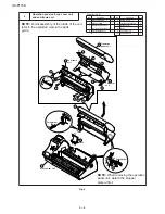
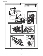
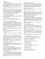
Fig. 2
Operation panel unit, top cover unit
and sub frame unit
2
Parts list (Fig. 2)
Hook
6
8
8
8
8
8
8
9
5
5
7
5
5
7
10
4
3
1
2
P-IN
lever
Screwdriver
Screwdriver
Operation
panel unit
Top cover
unit
Sub frame
unit
5
Screw (3x12)
4
6
Operation panel unit
1
7
Screw (3x10)
2
8
Hook
7
9
Top cover unit
1
10
Sub frame unit
1
No.
Part name
Qty
No.
Part name
Qty
1
Mechanism unit
1
2
Stopper plate
1
3
Operation panel unit/
top cover unit/ sub frame unit
1
4
Panel cable cover
1
NOTE:
For disassembly of the inside of the unit,
refer to the exploded view in the parts
guide.
NOTE:
When removing the operation
panel unit, detach the stopper
plate at first.
Mechanism unit