


UX-A255U
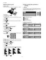
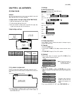
4. Volume adjustment
You can adjust the volume of the speaker, handset, and ringer using the
UP and DOWN arrow keys.
(1) Speaker
1. Press the SPEAKER key.
2. Press the UP or DOWN until the display shows the desired volume
level.
• Press SPEAKER key again to turn off the speaker.
(2) Handset
1. When talking through the handset, press UP or DOWN until the
display shows the desired volume level.
Display:
RECEIVER: HIGH
RECEIVER: MIDDLE
RECEIVER: LOW
(3) Ringer
1. Press the UP or DOWN key. (Make sure SPEAKER key has not been
pressed, the handset is not lifted, and a document is not loaded in the
feeder.)
Display:
RINGER: HIGH
RINGER: MIDDLE
RINGER: LOW
RINGER OFF: OK?
2. If you selected RINGER OFF: OK?, press START/MEMORY key.
CHAPTER 2. ADJUSTMENTS
[1] Adjustments
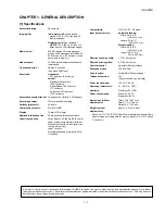
General
Since the following adjustments and settings are provided for this model,
make adjustments and/or setup as necessary.
1. Adjustments of output voltage (FACTORY ONLY)
1. Install the power supply unit in the machine.
2. Set the recording paper and document.
3. When the document is loaded, power is supplied to the output lines.
Confirm that outputs are within the limits below.
Output voltage settings
3. Settings
(1) Dial mode selector
DIAL mode (Soft Switch No. SW-B4 DATA No. 3)
Output
Voltage limits
+5V
4.25V ~ 5.75V
+24V
23.3V ~ 24.7V
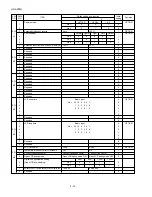
2. IC protectors replacement
ICPs (IC Protectors) are installed to protect the motor driver circuit.
ICPs protect various ICs and electronic circuits from an overcurrent con-
dition.
The location of ICPs are shown below:
1
+24V
2
+24V
3
MG
4
MG
5
DG
6
Vreg(+5V)
Connector
No.
CNPW
Pin No.
2 – 1
CONTROL PWB
(BOTTOM SIDE)
CNLIUA
FU100
CNPW
TEL/LIU PWB
(BOTTOM SIDE)
POWER
SUPPLY
PWB
(BOTTOM SIDE)
CONTROL
PWB
(TOP SIDE)
CNMT
CNLIUA
CNLIUA
CNPS
CNPW
CNPN
CNCIS
CNSP
CNCSW
CNTH
CNPRG
(step 1) Select "OPTION SETTING".
KEY : FUNCTION
DISPLAY: OPTION SETTING NUMBER OF RING
(step 2) Select "DIAL MODE".
KEY: Push until DIAL MODE is
indicated because the number of
's changes by the model.
DISPLAY: DIAL MODE 1=TONE, 2=PULSE
(step 3) Select, using "1" or "2".
KEY: 1
DISPLAY: TONE SELECTED
KEY: 2
DISPLAY: PULSE SELECTED
(step 4) End, using the "STOP" key.
KEY:
STOP
(1) FU100 (KAB2402) is installed in order to protect IC’s from an over-
current generated in the motor drive circuit. If FU100 is open, re-
place it with a new one.
↔
↔
↔
↔
• The ringer will ring once at the
selected level, then the date
and time will reappear in the
display.
↔
• Note: The volume reverts to
MIDDLE each time you
replace the handset.