background image

10

3  Operation

3.1.1.2  User menu

The measuring mode permits to use the following functions:


z

Zero point correction


z

Selection of the test mode


z

Start meas. resp. Store


z

Protocols.

These functions can be called up via the 

User menu

:


z

Press the   or   key for approx. two seconds.

The

 User


menu 

appears:

Zero point

Working order

Main test

Pre test

Regulator ins

Start meas.

Protocols

Exit

If the measurement time for the test of working order is zero, the 

user menu displays the menu item 

Store

 instead of the menu 

item 

Start meas.

.

The functions of the User menu are described in the chapters 

3.1.2 to 3.1.8.
To change between the menu items:


z

You can move up or down in the menu by pressing the appro-

priate   or   arrow key.


z

Confirm the selection by pressing the 

 key.

If the selection is not confirmed, the display returns to the mea

-

suring mode after a couple of seconds. 

Summary of Contents for miniLec 4

Page 1: ...Operating Instructions...

Page 2: ...sistance at any time Yours Hermann Sewerin GmbH Robert Bosch Stra e 3 33334 G tersloh Germany Tel 49 5241 934 0 Fax 49 5241 934 444 www sewerin com info sewerin com SEWERIN SARL 17 rue Amp re BP 211 6...

Page 3: ...equipment version HP Inlet for prelimi nary test Inlet for Main test Test of working order and Regulator inspections Buzzer Keyboard Outlet for Test of working order Suspension Signal light infrared...

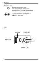
Page 4: ...the instrument on off keep pressed for approx 3 seconds Entries confirming a selection short pressing Changing between the operating menus Selection of menu items LCD Test mode Type of gas Battery st...

Page 5: ...Operating Instructions 26 10 2016 V3 XXX 103999 en MiniLec 4...

Page 6: ...to these instructions to avoid material damages Note This symbol refers to information and useful tips which are exceeding the basic operating proce dures CAUTION Danger of injuries This symbol refers...

Page 7: ...ng the zero point 11 3 1 3 Test of working order 12 3 1 3 1 Preparations 12 3 1 3 2 Execution 13 3 1 3 3 Analysis of working order 14 3 1 4 Main test 15 3 1 4 1 Preparations 15 3 1 4 2 Execution 16 3...

Page 8: ...eable alkaline batteries 39 5 Maintenance 40 5 1 Functional test inspection 40 5 2 Check to ensure the indication accuracy and leak tightness of the device 40 5 3 Adjustment 41 5 4 Maintenance and rep...

Page 9: ...hese operating instructions z z This product is exclusively destined for industrial and com mercial applications z z Repairs may only be performed by qualified experts or appro priately trained staff...

Page 10: ...t to changes The descriptions always refer to the default settings of the instrument 1 3 Intended usage The instrument can be used for the following purposes z z Serviceability determinations i e test...

Page 11: ...It is not required to change the type of gas z z It is required to use supply tubes with hydrophobic filters to protect the flow rate sensor applies to Test of working order i e serviceability determ...

Page 12: ...amiliar with the legal requirements in Germany TRGI are permitted to connect and operate the instrument The instrument can be connected to the gas installation with the help of three quick release con...

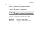
Page 13: ...instrument z z buzzer at the front panel of the instrument Note These signalling instruments cannot be switched off Every touch of a key is confirmed by an audible signal z z very long tone indicates...

Page 14: ...readings to a PC or other in struments e g printer pocket PC organizer It is located on the outer surface of the instrument below the red signal light To ensure an optimum data transmission you need t...

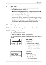
Page 15: ...em Hardware etc It is not possible to carry out a measurement when the extended settings are opened 3 1 Measuring mode 3 1 1 General information regarding the measuring mode 3 1 1 1 Switching on the d...

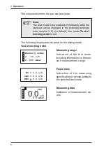
Page 16: ...is set The following display data depend on the testing mode Test of working order Measuring range Indication of the test mode including information on the sen sors measurement range Parameters Indic...

Page 17: ...n of the test mode including information on the sen sors measurement range Parameters Indication of the measuring specifications corresponding to the selected test mode Measuring data Indication of me...

Page 18: ...test Pre test Regulator ins Start meas Protocols Exit If the measurement time for the test of working order is zero the user menu displays the menu item Store instead of the menu item Start meas The f...

Page 19: ...oint is incorrectly set other values than zero are indicated on the display after switching on the instrument Note The zero point must be set for every individual test mode Perform the following steps...

Page 20: ...s streaming into the gas installation over a defined period of time leakage rate 3 1 3 1 Preparations There are different ways to install the instrument in the supply system see section 7 4 Flow measu...

Page 21: ...r than 0 minutes is specified For tests of the working order the measurement time is pre set ex works to zero minutes The menu item Store is indicated in the User menu instead of Start meas z z Confir...

Page 22: ...d up in the User menu via the menu item Protocols see section 3 1 8 3 1 3 3 Analysis of working order Depending on the relevant country there may be different national regulations for determining the...

Page 23: ...ulations with respect to main tests According to TRGI the following requirements have to be met z z The minimum test duration is 10 minutes z z During the test the pressure must not decrease Note The...

Page 24: ...approx 30 seconds The measurement is stored z z Confirm the displayed protocol with the key The Client Meter no menu appears z z If necessary use the or key to select the menu item Client no Enter a C...

Page 25: ...pipes are checked without fittings Note Fittings whose nominal pressure stage is at least equal to the testing pressure may be subjected to Preliminary test Depending on the relevant country there ma...

Page 26: ...e section 3 1 1 2 z z Wait for the temperature equalisation 3 1 5 2 Execution The device is in measuring mode z z Press the or key for approx two seconds to access the User menu z z Use the or key to...

Page 27: ...enu item Client no Enter a Client no max 6 digits z z If necessary use the or key to select the menu item Meter no Enter a Meter no max 8 digits z z Use the or key to select the menu item Continue The...

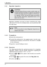
Page 28: ...e instrument Note It is not possible to select Regulator inspection as default start mode 3 1 6 1 Preparations z z Switch the instrument on z z Connect the instrument to the supply system Use the corr...

Page 29: ...ol The instrument returns to the Regulator ins menu Note If you select Exit in the dialogues of the individual tests no values will be stored for the protocol z z Carry out further individual tests in...

Page 30: ...e stored protocols can be called up in the User menu via the menu item Protocols see section 3 1 8 3 1 6 3 Dynamic pressure This test is used to check the regulation function of the gas regu lator wit...

Page 31: ...heck the safety shut off valve for leaks If you want to skip the zero shut off test z z Select the option none z z An appropriate entry is gener ated in the protocol 3 1 6 7 Low pressure cut off valve...

Page 32: ...rting a measurement Starting a measurement can be simplified provided that the ap plied pressure is greater than 5 mbar z z Press the key and release it quickly The measurement starts If the described...

Page 33: ...Protocols z z Confirm the selection with the key A brief message appears indicating the number of stored pro tocols Then the last stored protocol is displayed Examples Preliminary Test Main test Test...

Page 34: ...xecution of the commands Print Send and Send all it is required to align the MiniLec 4 with the receiving instrument see chapter 2 3 If no receiving instrument is detected the search run is interrupte...

Page 35: ...e and keys for approx 2 seconds The instrument is in the measuring mode z z Press simultaneously the and keys for approx 2 seconds The following display appears The access is protected by a PIN code A...

Page 36: ...PIN code it is required to contact the SEWERIN service The PIN code has to be entered from left to right The currently active digit is always indicated on a black background z z Select the desired di...

Page 37: ...o menu top level Use the or key to navigate within a menu Use the key to confirm the selected menu item On the two first menu levels the menu item Exit is always indi cated at the end of a menu If thi...

Page 38: ...ground Use the or key to increase or decrease the value Use the key to confirm the selected value Note It is always required to confirm all values Values can only be specified in forward direction It...

Page 39: ...ing mode 3 2 3 1 Adjustment menu The Adjustment menu is used for setting the sensors CAUTION The instrument may only be adjusted by sufficiently qualified members of staff Incorrect adjustments may re...

Page 40: ...e due inspection has been performed and confirmed the instrument can be re used for measurements System Date time Date format INS interval INS block PIN code User name Language Exit no PIN 0000 Leakag...

Page 41: ...ivery weeks 00 yes City Council Frank Smith Deutsch English Espa ol no PIN 0000 Leakage Delivery DD MM YYYY YYYY MM DD weeks 00 yes City Council Frank Smith Deutsch English Espa ol no PIN 0000 Leakage...

Page 42: ...H2 0 00 0 Accu Ni MH Alkaline mAh 1850 sec 010 0 100 Working order Main test Pre test CH4 C3H8 C4H10 TGAS H2 0 00 0 Accu Ni MH Alkaline mAh 1850 sec 010 0 100 Working order Main test Pre test CH4 C3H...

Page 43: ...d limit values Parameter Working order mbar param bar param Exit 3 2 3 5 Memory menu The Memory menu is used to delete the recorded measurements No other settings are affected by this Memory Clear Exi...

Page 44: ...ating time is indicated correctly the following settings need to be modified in the extended settings z z Accu type Info menu Hardware Battery z z Capacity of the used accumulator types Info menu Hard...

Page 45: ...z Vehicle cable M4 12 V mounting z z Vehicle cable M4 12 V mobile z z Vehicle cable M4 24 V mobile Note You can connect up to three docking stations to a single 100 240 V power supply unit If four or...

Page 46: ...nt and put it into the docking station z z The accumulators are completely discharged After the dis charging procedure the instrument automatically changes to recharging A complete recharge discharge...

Page 47: ...s Proceed as follows to replace batteries or accumulators z z Loosen the two lower screws on the back panel of the instru ment using the supplied screwdriver z z Open the battery compartment z z Inser...

Page 48: ...the device z z Function of controls z z Battery charge status z z Zero point 5 2 Check to ensure the indication accuracy and leak tightness of the device The indication accuracy and the leak tightness...

Page 49: ...n for use This setting can be adjusted in the Adjustment menu Note The adjustment settings can be reset in the Hard ware menu under Reset 5 4 Maintenance and repair The device must only be serviced an...

Page 50: ...5 13 W SPAN ADJUSTMENT An error occurred during adjusting the flow rate Check the flow rate Repeat adjustment See section 3 2 3 1 and 5 14 M SPAN ADJUSTMENT An error occurred during adjusting the pres...

Page 51: ...0 C 70 C Pressure 860 1100 hPa Permissible realative humidity 0 90 r h non condensing Sensors Flow rate sensor for Test of working order Pressure sensor for Test of working order Main test Preliminary...

Page 52: ...mbar Resolution 0 1 mbar Measuring error 5 of end of measuring range Used for Preliminary test Measuring range 0 2 bar Resolution 0 001 bar Measuring error 5 of end of measuring range Flow rate senso...

Page 53: ...Flow rate 0 5 l h Operating pressure approx 20 30 mbar Preliminary test Gas Air Pressure approx 1 0 bar Legende 1 Main stop device closed open 2 Meter locking device 3 Equipment locking device 4 Cons...

Page 54: ...approx 150 mbar Check of non metered pipes Gas Natural gas Flow rate 0 5 l h Operating pressure approx 20 30 mbar Test of working order at an arbitrary place of the pipe Gas Natural gas Flow rate 0 5...

Page 55: ...spection Dynamic pressure Main stop device open Gas Natural gas Operating pressure approx 20 30 mbar Legende 1 Main stop device closed open 2 Meter locking device 3 Equipment locking device 4 Consumer...

Page 56: ...ion pressure inspection Main stop device closed Gas Air Pressure depending on the upper switching off point of the safety shut off valve typi cal 50 100 mbar Regulator inspection Zero shut off Main st...

Page 57: ...e open Gas Natural gas Operating pressure slowly increasing to approx 20 30 mbar Legende 1 Main stop device closed open 2 Meter locking device 3 Equipment locking device 4 Consumer switched off 5 Cont...

Page 58: ...erwritten Entry starts with a blanc black block Letters A Z can be chosen in alphabetical order with key After reaching letter Z the menu starts again with letter A Letters Z A can be chosen downwards...

Page 59: ...letter A When pressing key the previous letter of the alphabet appears all others appear in descending order After letter A the additional characters 9876543210 are displayed The chosen letter is conf...

Page 60: ...nspection Connection Rectus 20 nipple z z Test of working order Connection Inlet Rectus 20 nipple Outlet Rectus 20 coupling z z Data memory z z Infrared interface MiniLec 4 version LP Part No LH04 100...

Page 61: ...VT z z with foam insert and com partments for multi purposes z z to accommodate the following MiniLec 4 Charging technique Printer Test hoses Test connections Feeding devices SPL Pumps Docking station...

Page 62: ...r Main test and Test of work ing order Outlet hose Part No LH04 Z0200 z z Instrument Rectus 20 nipple z z Installation Rectus 21 coupling z z Length 1 5 m z z incl hydrophobic filter z z for Main test...

Page 63: ...ipe gas meter e g DN 25 G 1 Part No LH04 Z1900 z z with ball valve and Rectus 21 nipple z z for connections with swivel nuts z z 2 pcs are always required z z other dimensions available Overflow cap D...

Page 64: ...each other z z for all test types Y piece with two ball valves Part No LH04 Z2300 z z 1 x coupling Rectus 21 2 x nipple Rectus 21 z z for Preliminary test optional also for other tests Feeding device...

Page 65: ...00 z z Software for the central re cording processing and man aging of measurement data on the PC Test set MiniLec 4 HP Part No ZP08 10000 z z for checking pressure sensors and flow rate sensor of the...

Page 66: ...rmity Hermann Sewerin GmbH hereby declares that the MiniLec 4 fulfils the requirements of the following guideline z z 2014 30 EU G tersloh 2016 04 20 Dr S Sewerin General Manager The complete declarat...

Page 67: ...cessories Description of waste Allocated EWC waste code Device 16 02 13 Test gas can 16 05 05 Battery accumulator 16 06 05 Old instruments Old instruments can be returned to Hermann Sewerin GmbH We wi...

Page 68: ...d Wasserfaches e V Ger man Technical and Scientific Association for Gas and Water IrDA Infrared Data Association interface standard used for com munication LCD Liquid Crystal Display NiMH Nickel metal...

Page 69: ...st of working order 4 Contrast 34 D Data transmission 6 Date format 32 Device inspection 40 Docking station 36 DVGW 2 E Error message 42 Extended settings 27 F Firmware Version 7 G Gas 3 H Hardware me...

Page 70: ...nsmitting 25 Viewing 25 Protocols menu 26 R Regulator inspection Execution 20 Preparations 20 Repair 41 Reset 35 S Sensors 34 44 Servicing 40 Signal light 5 43 Signal tone 5 Storage temperature 3 Syst...

Page 71: ...Hermann Sewerin GmbH Robert Bosch Stra e 3 33334 G tersloh Germany Telefon 49 5241 934 0 Telefax 49 5241 934 444 www sewerin com info sewerin com 26 10 2016 a V 3 XXX 103999 en...

Reviews: