


Operating Instructions – MOVITRAC® B
57
4
Installing accessories and options – electrical aspects
Installation
•
NOTICE
Potential shift
Possible consequences include malfunctions that could lead to irreparable damage
to the unit.
– There must not be any potential shift between the connected units. Take appro-
priate measures to avoid potential shift, such as connecting the unit ground con-
nectors using a separate cable.
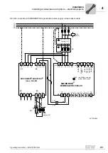
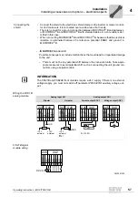
Wiring the FIO11B
analog module
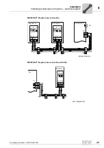
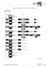
FIO21B digital
module wiring
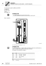
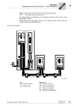
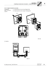
Connecting the
shield
• Connect the shield to the electronics shield clamp on the inverter or master control-
ler and make sure it is connected over a wide area at both ends.
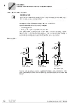
• There is no need for a ground connection between MOVITRAC
®
B and gateways,
or MOVITRAC
®
B and MOVITRAC
®
B with shielded cables. A 2-core cable is per-
mitted in this case.
• When connecting MOVIDRIVE
®
B and MOVITRAC
®
B, be aware that the electrical
isolation is eliminated between the reference potential DGND and ground in
MOVIDRIVE
®
B.
INFORMATION
The FIO21B and FSE24B front modules require a 24 V supply. If there is no external
voltage supply, you must not switch off parameter
P808 24VIO auxiliary voltage out-
put
.
Analog input AI1
Analog output AO1
Bipolar
Unipolar
Current output AOC1
Voltage output AOV1
R
L
≤
750
Ω
X45 X40
1 2 3 4 5
H L
⊥
RS-485+
RS-485–
GND
AI2
AOV1
GND
GND
AOC1
GND
–10 V
external
+10 V
external
X45 X40
1 2 3 4 5
H L
⊥
RS-485+
RS-485–
GND
AI2
AOV1
GND
GND
AOC1
GND
+10 V
external
or
X10:1
X45 X40
1 2 3 4 5
H L
⊥
RS-485+
RS-485–
GND
AI2
AOV1
GND
GND
AOC1
A
R
L
X45 X40
1 2 3 4 5
H L
⊥
RS-485+
RS-485–
GND
AI2
AOV1
GND
GND
AOC1
V
3833241355
X46
X42
1 2 3 4 5
H L
⊥
CAN +
CAN –
GND
DI10
DI13
DI1
1
DI12
DI14
6
DI15
7
DI16
V
DC 24 V
Summary of Contents for Movitrac B
Page 2: ...SEW EURODRIVE Driving the world...
Page 259: ......


