


12
Functional safety
Safety conditions
Operating Instructions – MOVIGEAR
®
performance
368
•
The STO signal (F_STO_P1, F_STO_P2, and F_STO_M) may not be used for
feedback.
•
For safety controller/safety relays, you must only use grounded voltage sources
with protective electrical separation (PELV) according to EN 61131-2 and
EN 60204-1.
•
If several voltage sources are used, each voltage source must be connected to a
PE system.
•
When planning the installation, observe the technical data of the electronics cover.
•
When the STO control cables are routed to Terminal X9 in the electronics cover,
the cable ends must be covered with conductor end sleeves and the cables must
be fixed close to the terminal X9 using cable ties. Other the low-voltage signals
can be bundled together with the STO signals.
•
Do not use the port 24 V_OUT of the electronics cover for safety-related applica-
tions. This voltage is only permitted to supply the M12 plug connector X5504 when
the STO jumper is plugged in.
•
To use the drive unit in safety-related applications, remove the jumpers labeled
with "Caution, remove jumper for safety operation" from the STO terminal X9. No
labeled jumpers are available for those designs where the STO connection is per-
formed using plug connectors. The installed jumper is relevant to the function.
12.3.3
Requirements on the external safety controller
A safety relay can be used as an alternative to a safety controller. The following re-
quirements apply analogously.
•
The safety controller and all other safety-related subsystems must be approved for
at least the safety class that is required in the overall system for the respective ap-
plication-related drive safety function.
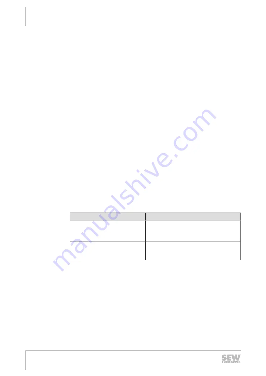
The following table shows an example of the required safety class of the safety
controller:
Application
Safety controller requirements
Performance level d according to
EN ISO 13849-1, SIL 2 according to
EN 62062
Performance level d according to
EN ISO 13849-1
SIL 2 according to EN 61508
Performance level e according to
EN ISO 13849-1, SIL 3 according to
EN 62061
Performance level e according to
EN ISO 13849-1, SIL 3 according to
EN 61508
•
The wiring of the safety controller must be suitable for the required safety class
(see manufacturer documentation). The STO input of the electronics cover can be
switched with 2 poles (sourcing output, sourcing/sinking, or serial sourcing), or with
1 pole (sourcing).
•
The values specified for the safety controller must be strictly adhered to when
designing the circuit.
•
Electro-sensitive protective equipment (such as light grid or scanner) according to
EN 61496‑1 and emergency stop buttons must not be directly connected to the
STO input. The connection must be made using safety relays, safety controllers
etc.
25887548/EN – 04/2019
Summary of Contents for MOVIGEAR MGFx-DSI Series
Page 2: ...SEW EURODRIVE Driving the world...
Page 404: ......
Page 405: ......
Page 406: ......
Page 407: ......


