


12
MOVILINK
®
device profile
Coding of the process data
Manual – EtherCAT
®
Interfaces, Field Distributors
92
12
MOVILINK
®
device profile
12.1
Coding of the process data
The same process data information is used for control and setpoint selection in all
fieldbus systems. The coding of the process data takes place according to the uniform
MOVILINK
®
profile for SEW‑EURODRIVE drive inverters.
Two variants can generally be distinguished for MOVIMOT
®
drives operated on
the ..Z.1, ..Z.3, ..Z.6, ..Z.8 or ..Z.9 field distributors:
•
2 process data words (2 PD)
•
3 process data words (3 PD)
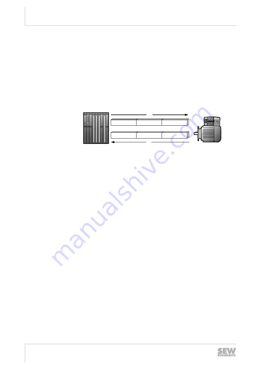
MOVIMOT
®
PO1
PO2
PO3
Master
PI1
PI2
PI3
PO
PI
1191917323
PO
= Process output data
PI
= Process input data
PO1 = Control word
PI1
= Status word 1
PO2 = Speed (%)
PI2
= Output current
PO3 = Ramp
PI3
= Status word 2
12.1.1
2 process data words
For controlling the MOVIMOT
®
inverter via 2 process data words, the higher-level con-
troller sends the process output data "Control word" and "Speed [%]" to the
MOVIMOT
®
inverter. The MOVIMOT
®
inverter sends the process input data "Status
word 1" and "Output current" to the higher-level controller.
12.1.2
3 process data words
When control uses 3 process data words, the ramp is sent as the additional process
output data word and status word 2 is sent as the third process input data word.
12.1.3
Process output data
Process output data is sent from the higher-level controller to the MOVIMOT
®
inverter
(control information and setpoints). They only take effect in the MOVIMOT
®
inverter if
the RS485 address in the MOVIMOT
®
inverter (DIP switches S1/1 to S1/4) is set to a
value other than "0".
The MOVIMOT
®
drive can be controlled via the following process output data:
•
PO1: Control word
•
PO2: Speed [%] (setpoint)
•
PO3: Ramp
25809148/EN – 01/2019