


8
Project planning
MFE status word
Manual – EtherCAT
®
Interfaces, Field Distributors
75
8.4
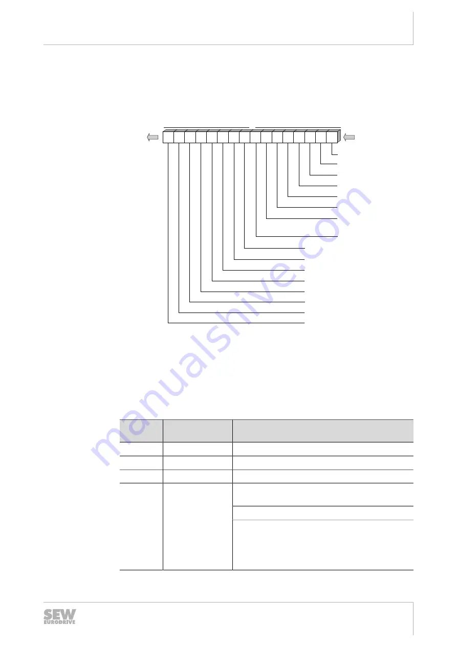
MFE status word
The following figure shows the assignment of the status word of the MFE fieldbus in-
terface:
15 14 13 12 11 10
9
8
8: Overload actuator voltage DO0
7
6
5
4
3
2
1
0
9: Overload actuator voltage DO1
10: Reserved = 0
11: Reserved = 0
12: Overload sensor voltage I
13: Reserved = 0
14: Reserved = 0
15: Reserved = 0
1: Reserved = 0
0: Reserved = 0
Bus
master
MFE
2 Byte MFE status
Byte n+1
Byte n
MFE
status
7: System error MFE
2: Reserved = 0
3: Reserved = 0
4: Reserved = 0
5: Reserved = 0
6:
Monitoring
encoder cable
9801723275
The following table shows the diagnostics information of the MFE fieldbus interface set
up for evaluation in the higher-level PLC application. The signals are transferred to the
controller via parameters and via the process data channel.
The logical communication status "0" signals the status "OK" for each signal to ensure
that no asynchronous startup sequences from the bus master and the PLC can cause
incorrect diagnostic messages when the systems are started up (bus startup with user
data = 0).
MFE
status bit
Diagnostics
name via bus
Function and coding
0
Reserved
–
1
Reserved
–
2
Reserved
–
6
Encoder line moni-
toring
1 = Error in encoder line (wire break) or encoder
axis not turning.
0 = No error
The two encoder cables are checked for wire
breaks. The cables are only monitored when the
MOVIMOT
®
inverter is enabled. Response time is
1.5 s. This status bit remains set until the
MOVIMOT
®
controller enable is reset.
25809148/EN – 01/2019