50
Operating Instructions – Explosion-Proof CMP Synchronous Servomotors
10
Overhung loads and axial loads
Technical Data
10.5 Overhung loads and axial loads
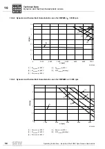
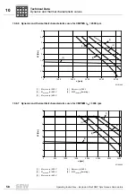
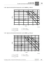
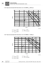
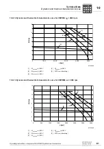
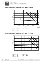
The following overhung loads are determined by subjecting the shaft to a load with the
rated torque.
The permitted overhung loads F
q
at point x (distance from the shaft shoulder to the ap-
plication point) are determined using the diagrams below. The diagrams are based on
the following nominal bearing service life:
10.5.1 Permitted overhung and axial loads
Motor type
Nominal bearing service life
CMP40
L10h = 25000 h
CMP50
L10h = 25000 h
CMP63
L10h = 20,000 h
05590AXX
Figure 2: Determining the overhung load F
R
R
Motor type
F
q max
[N]
Mean speed
1)
[rpm]
1) The mean speed must, for example, be determined from the travel diagram.
F
A
[N]
1500
3000
4500
6000
CMP40S
F
q max
264
260
225
205
F
A
109
86
74
68
CMP40M
F
q max
264
264
245
220
F
A
116
92
81
73
CMP50S
F
q max
400
315
250
200
F
A
157
104
83
66
CMP50M
F
q max
400
355
275
220
F
A
168
117
91
73
CMP50L
F
q max
400
370
280
225
F
A
182
122
92
74
CMP63S
F
q max
578
460
360
290
F
A
170
115
90
72.5
CMP63M
F
q max
578
500
380
300
F
A
188
125
95
75
CMP63L
F
q max
578
560
445
360
F
A
208
140
111
90
P
i
f
kVA
Hz
n
Summary of Contents for CMP40
Page 2: ...SEW EURODRIVE Driving the world ...
Page 86: ......


