5
Electrical installation
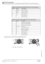
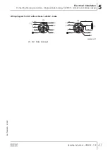
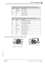
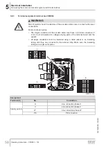
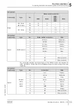
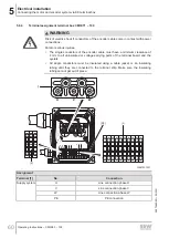
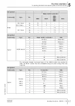
Connecting the plug connectors – Single-cable technology for CM3C.. motors in encoderless design
Operating Instructions – CM3C63 – 100
51
5.7.4
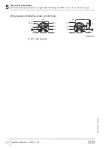
Wiring diagrams of the brake control with BK../BZ.D brake
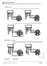
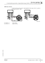
In every application, the BK.. holding brake can be controlled via the BMV brake relay
or a customer relay with varistor overvoltage protection.
If the system complies with the specifications for direct brake control, then a BK05 and
BK06 brake at the CM3C63 servomotor can also be controlled directly via the brake
output of a MOVIDRIVE
®
modular application inverter.
BMV brake controller
BMV
1
2
3
4
13
14
15
SH1
K12
+
-
U
DC 24 V
IN
DC 24 V
+
-
+ -
D
B
A
H
L
C
V
W
U
[A]
+
-
BK3
BK1
34755470603
Connection 1, 2
Power supply
Connection 3, 4
Signal (inverter)
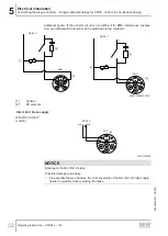
Direct 24 V brake supply with non-SEW inverters
If the brake is not controlled via BMV brake control unit, a contactor must be used that
is suitable for switching inductive DC loads. In this case a varistor circuit in parallel to
the brake coil is required as overvoltage protection and EMC interference suppression
of the 24 V supply. For brakes with external DC supply of more than 24 V and without
BMV, a 300 V varistor must be used.
26870460/EN – 05/2021


