


Manual – XFE24A EtherCAT Fieldbus Interface
47
7
Settings in the EtherCAT master
Motion Control via EtherCAT
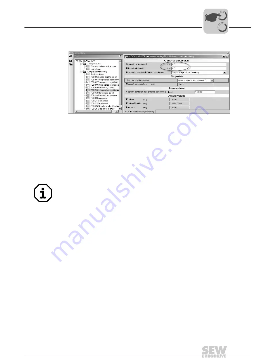
Configuration of
the FCB10 (inter-
polated position-
ing)
Set the cycle time of your EtherCAT controller in the controller setpoint cycle parameter,
e.g. 1 ms.
The position setpoints of the controller are smoothed with these configurable mean val-
ue filters for a "steady", continuous speed curve.
In addition to that, the source for the position setpoint must be set, here: process data
buffer channel 0.
OUT process data
The configuration of the OUT process data is identical to the configuration of the Velocity
mode, more information is available there.
Travel distance:
1.0000 [Revolutions]
Velocity:
1 [1/min]
7.2
Settings in the EtherCAT master
For time slice synchronization, you must activate the function
Distributed Clock
. The bus
cycle of the MOVIAXIS
®
must correspond exactly to that of the external controller, which
was set during startup. Please also check the watchdog for timeout monitoring only for
sync manager 0x1000 (output data). The watchdog for timeout monitoring is set to a de-
fault value.
7.2.1
Settings for Velocity mode
• The speed setpoint is transferred via the input word configured in the PDO Editor.
• The position is transferred via the output word configured in the PDO Editor. The
resolution is set during startup.
11669AXX
Figure 25: Configuration of the FCB10
The unit and resolution of the speed or velocity and position, or travel of the axis, de-
pends on the settings of the user travel units, which were made during startup. If no oth-
er user travel units were defined, they are as follows:
0
0
I
Summary of Contents for 1821 2492
Page 2: ...SEW EURODRIVE Driving the world...
Page 66: ......