


Manual – XFE24A EtherCAT Fieldbus Interface
25
6
Control of the MOVIAXIS® multi-axis servo inverter
Operating Behavior on EtherCAT
6
Operating Behavior on EtherCAT
This section describes the basic behavior of the servo inverter on the EtherCAT system
when controlled via permanently configured PDOs for fieldbus communication.
6.1
Control of the MOVIAXIS
®
multi-axis servo inverter
The MOVIAXIS
®
multi-axis servo drive is controlled via the permanently configured
PDOs, which are up to 16 I/O words in length. When using an EtherCAT master, the pro-
cess data words are directly mapped in the process image and can so be addressed di-
rectly by the control program.
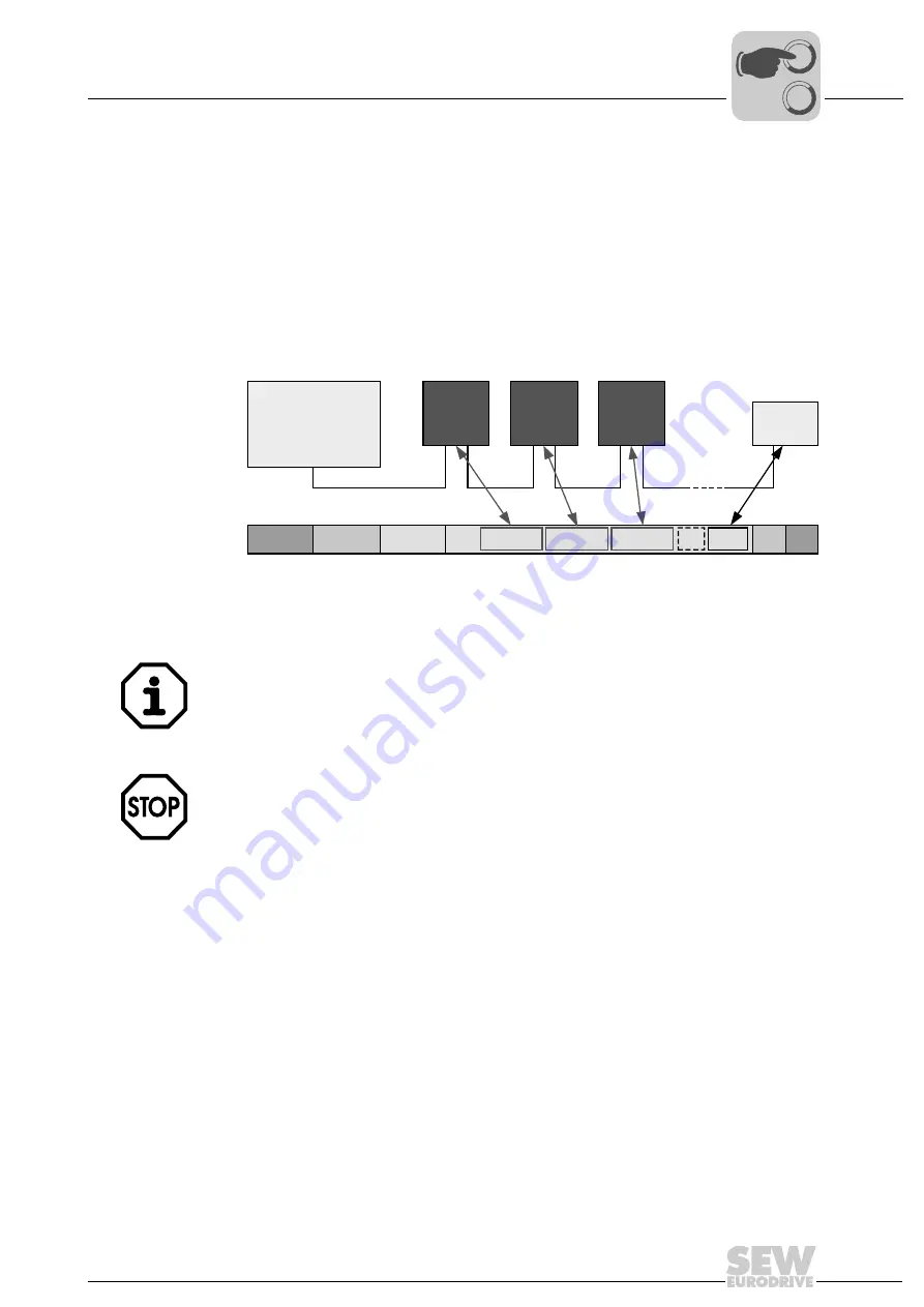
61375AXX
Figure 9: EtherCAT with SEW drives
SEW
Drive
Ether
CAT
Ethernet
Header
Frame
Header
EtherCAT
Header
Data
...
EtherCAT
M aster
SEW
Drive
SEW
Drive
FCS
I/O
Drive 1 Drive 2 Drive 3
For more information about controlling via the process data channel, in particular re-
garding the configuration of the control and status words, refer to the "MOVIAXIS
®
Multi-
Axis Servo Inverter" project planning manual.
For proper operation of synchronized applications, timing requirements must be met by
the master depending on the synchronization mechanism.
•
Synchronization via Distributed Clock (DC):
The process data telegram must arrive shortly before the DC. Beckhoff recommends
a maximum time of 10 % (in relation to the DC cycle) before the DC.
•
Synchronization via synchronized process data:
The MOVIAXIS
®
servo system can handle a maximum jitter of the EtherCAT process
data telegram (setpoints of the master, etc.) of ± 40 µs. If this jitter limit is exceeded,
a synchronous processing is no longer guaranteed. Please check the synchroniza-
tion quality of your EtherCAT master if problems occur.
0
0
I
Summary of Contents for 1821 2492
Page 2: ...SEW EURODRIVE Driving the world...
Page 66: ......