background image

5 – Installation and set-up 

MultiExact Gas Analyser 

5.4.7  Changing regional settings 

You can configure the following analyser regional settings so that the information 
shown on the various screens is better suited to your local conventions: 

Setting 

Options available 

Language 

Various languages are supported 

Date format 

Day/Month/Year * or Month/Day/Year 

Decimal format 

Use of "." * (full stop) or "," (comma) as the decimal point 

*  Default option. 


To change the regional settings: 

1. 

Select 


 Settings 

 Regional. 

2. 

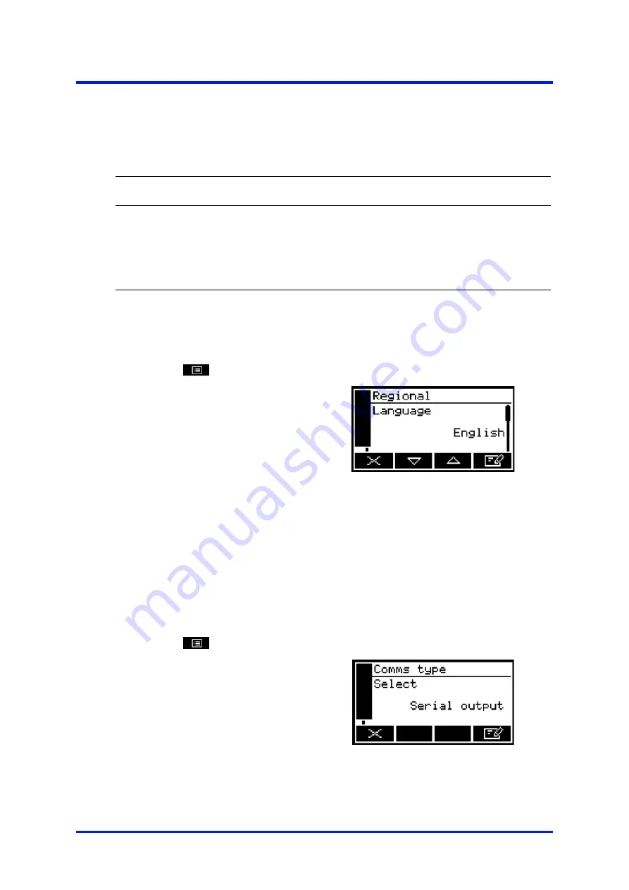
This screen shows the first 
regional option (Language). 


Figure 26 – The regional settings 

(language) option screen 


5.4.8  Selecting communications type 

☞ 

If your analyser supports digital communication e.g. Modbus ethernet, RS485 
etc. the communications type will default to this. You can however, choose to 
select Serial Output (RS232). If serial output is selected then digital 
communication over Modbus is disabled. See Appendix A4. 


1. 

Select 


 Set up 

 Comms Type. 

2. 

This screen shows the first 
communications type. 


Figure 27 – The Communications   

type screen 


40 

05410001A / Revision 6 

Summary of Contents for SERVOPRO MultiExact

Page 1: ...Part Number 05410001A Revision 6 Language UK English Operator Manual SERVOPRO MultiExact Gas Analyser PROCESS ANALYSERS ...

Page 2: ...This page intentionally blank ...

Page 3: ...rmation screen 19 4 10 Editing on screen data 20 5 INSTALLATION AND SET UP 21 5 1 Mechanical installation 21 5 1 1 Bench mounting 21 5 1 2 Panel mounting 21 5 1 3 Rack with slide mounting 23 5 1 4 Valve block connections option 26 5 2 Electrical Installation 27 5 2 1 Electrical Safety 27 5 2 2 Analogue output connections 28 5 2 3 Fault and range relay connections 29 5 2 4 Alarm and status relay co...

Page 4: ...ity or control only 57 5 9 1 Overview of measurement errors 57 5 9 2 Entering a cross interference X Interference compensation 58 5 10 Selecting display units 58 5 11 Configuring the measurement alarms 60 5 11 1 Alarm modes and levels 60 5 11 2 Latching non latching alarms 62 5 11 3 Hysteresis levels 62 5 11 4 Viewing the measurement alarm status 63 5 12 Setting up the flow alarm option 64 6 CALIB...

Page 5: ...ges 90 9 3 Diagnostics 91 9 4 General fault finding 92 10 STORAGE AND DISPOSAL 95 10 1 Storage 95 10 2 Disposal 95 11 SPARES 96 A1 RS232 CONNECTION DETAILS 97 A1 1 Overview 97 A1 2 Connecting the analyser to a PC 98 A1 3 Configuring the RS232 serial output parameters 98 A1 4 Capturing data using Windows and Hyper Terminal 99 A1 5 Configuration transfer 100 A2 SERIAL OUTPUT FORMATS 103 A3 IMPLEMENT...

Page 6: ...formance data O2 trace measurement 127 A9 4 Performance data 0 10ppm CO2 measurement 128 A9 5 Performance data 0 500ppm CO2 measurement 129 A9 6 Performance data 0 10ppm CO measurement 131 A9 7 Performance data 0 20ppm N2O measurement 132 A9 8 Performance data 0 50ppm CH4 measurement 133 A9 9 Performance data TCD 134 A9 10 Performance data flow alarm 135 A10 RECOMMENDED CALIBRATION PERIODS 136 A11...

Page 7: ...use or maintain the analyser Important safety information is highlighted in this manual as WARNINGs and CAUTIONs which are used as follows WARNING Warnings highlight specific hazards which if not taken into account may result in personal injury or death CAUTION Cautions highlight hazards which if not taken into account can result in damage to the analyser or to other equipment or property This man...

Page 8: ...a selection of digital communications Modbus RS485 or TCP and Profibus The analyser conforms to the requirements of the NAMUR Normenarbeitsgemeinschaft für Mess Und Regeltechnik in der Chemischen Industrie standards NE43 4 20 mA output and NA64 status outputs The analyser is simple to operate with an intuitive user interface The analyser is 3U in height and is suitable for 19 inch rack panel or be...

Page 9: ...oft key 2 10 Alarm LED 11 Soft key 1 12 Sample 2 bypass flowmeter 13 Sample 2 flowmeter 14 Sample 1 bypass flowmeter 15 Sample 1 flowmeter TCD O2 purity and O2 control transducers only Pressure driven transducers only Figure 1 Front of the analyser A SERVOMEX SERVOPRO MultiExact Serial No 05410 P0001 SERVOMEX FILTER FILTER Bypass Sample SERVOPRO MultiExact Serial No 05410 P0001 SERVOMEX 1 2 3 4 5 ...

Page 10: ...nector option 17 RS485 connector option 18 Caution refer to manual symbol 19 RS232 connector 20 Earth ground symbol 21 Transducer 2 sample gas outlet 22 Transducer 2 sample gas outlet 23 Transducer 1 sample gas outlet CO CO2 N2O and CH4 trace transducers and valve block TCD O2 trace O2 purity and control transducers Analysers configured for 2 measurements only This product has been tested to the r...

Page 11: ... 19 in Bench mounted analyser L x H x W 478 x 146 x 435 mm 18 8 x 5 7 x 17 in 478 x 180 x 435 mm 18 8 x 7 x 17 in Mass 12 kg Electrical supply requirements See Section 2 3 Without 19 inch rack mounting brackets With 19 inch rack mounting brackets fitted With front mounting feet retracted With front mounting feet extended 2 2 Environmental limits Equipment is suitable for indoor use only Ambient te...

Page 12: ... to 20 mA Fault condition 0 mA or 21 5 mA Under range 0 4 mA Voltage output active Maximum load resistance 100 K Ohms Isolation voltage to earth 500 V ac or dc Output range Normal sample measurement 0 to 10 V Fault condition 0 or 10 75 V Under range Not applicable Signal voltage mA RS485 output terminals suitable for Flexible conductors 0 5 to 1 5 mm 20 to 16 AWG Solid conductors 0 5 to 1 0 mm 20 ...

Page 13: ...ml min 1 Dew point 5 C below ambient temperature minimum Temperature 5 to 45 C Particulate size 2 µm 2 micron Infrared GFX transducer trace Flow rate 200 to 500 ml min 1 Dew point 5 C below ambient temperature minimum Temperature 5 to 45 C Particulate size 2 µm 2 micron Thermal Conductivity transducer Flow rate 100 to 200 ml min 1 Dew point 5 C below ambient temperature minimum Temperature 5 to 45...

Page 14: ...ended Low calibration setpoint 0 99 5 O2 0 zero grade nitrogen recommended Minimum difference 0 5 Low calibration tolerance level Calibration gas 5 O2 Calibration gas 5 O2 0 5 O2 10 O2 High calibration tolerance level Calibration gas 5 O2 Calibration gas 5 O2 0 5 O2 10 O2 O2 control transducer calibration gases High calibration setpoint 0 5 100 O2 Low calibration setpoint 0 99 5 O2 0 zero grade ni...

Page 15: ...cer calibration gases High calibration setpoint 18 to 25 O2 Low calibration setpoint 0 01 ppm to 5000 ppm O2 Minimum calibration difference between low and span 17 5 O2 Low calibration tolerance level 10 O2 High calibration tolerance level 10 O2 The low calibration gas must be a high quality certified mixture usually nitrogen N6 0 containing trace Oxygen Mixtures between 1000 ppm to 4000 ppm are p...

Page 16: ...ed from Servomex to ensure a representative sample is being measured for control systems CAUTION The sample and bypass flowmeters are calibrated for use with air as the background gas When fitted for the analysis of CH4 in Helium the flowmeter reading should be multiplied by a factor of 2 7 to provide the correct flow rate 10 05410001A Revision 6 ...

Page 17: ...nd check that they are not damaged If any item is damaged immediately contact Servomex or your local Servomex agent 4 Check that you have received all of the items that you ordered If any item is missing immediately contact Servomex or your local Servomex agent 5 If you do not intend to use the analyser immediately Refit any protective plastic covers Place the analyser and any other equipment supp...

Page 18: ...an alarm condition exists see Section 5 11 Fault LED On when a fault condition exists see Section 9 4 2 Start up and measurement screens When you first switch on the analyser a start up screen is displayed while the analyser carries out a self test The start up screen shows the Servomex name a self test time elapsed remaining indicator and messages identifying the tasks being carried out as part o...

Page 19: ...easurement Alarm icon see Section 5 11 1 mA Range see Section 5 7 1 Fault icon see Section 9 Soft key legends Status icon bar see Section 4 4 Transducer number 1 always shown Software health indicator Gases being measured Measurement units Pressure compensation indicator Current measurement 1 Service in progress icon see Section 6 2 2 mA Ranges see Section 5 7 1 Current measurement 2 Maintenance r...

Page 20: ... Section 4 6 4 3 Soft key legends The four soft key legends at the bottom of the measurement screen Figure 3 correspond to the four soft keys on the front of the analyser The first left most legend corresponds to the function of soft key 1 the second legend corresponds to the function of soft key 2 and so on On the measurement screen the soft key functions are as follows Legend Meaning Function wh...

Page 21: ... editing Left Moves the cursor left Right Moves the cursor right Stop Stops an automatic validation calibration 4 4 System and measurement status icons System status is on the status icon bar and can be shown with a fault icon or a maintenance required icon see table below Measurement status is on the right hand side of the measurement reading and can be shown with a fault icon a maintenance requi...

Page 22: ...sword protected this means that the correct corresponding password has to be entered before the option screen can be accessed See Section 5 4 1 for details on how to set the security level Password protection operates as follows As supplied the security level is set to high the supervisor password is set to 2000 and the operator password is set to 1000 The first time you try to access a password p...

Page 23: ...MultiExact Gas Analyser 4 Analyser user interface Figure 4 The analyser menu structure 05410001A Revision 6 17 ...

Page 24: ...pensation on off 7 2 2 select the display units 5 10 set up the mA output parameters and range 5 7 3 and set up the voltage output parameters and range 5 8 1 and set up the flow alarm 5 12 Calibrate Select this screen to calibrate or validate the analyser 6 6 2 and to view calibration history 6 2 4 Alarm Select this screen to set up the measurement alarms and set the alarm follow options 5 11 1 un...

Page 25: ...tings language and so on 5 4 7 Backlight Adjusting the backlight timer duration 5 4 5 Contrast Adjusting the contrast of the screen 5 4 4 Security Selecting the security level 5 4 2 Information Viewing analyser system information 4 9 Alternatively press the soft key to display the menu screen again 4 9 The information screen This screen shows information such as the analyser serial number and the ...

Page 26: ...en changes to show the corresponding edit screen with the first digit highlighted Figure 8 A typical edit screen When the first digit is highlighted press the soft key to exit the menu without changing the data Alternatively use the soft keys to edit the data as follows Soft key Function Increases the highlighted digit by 1 Decreases the highlighted digit by 1 Moves the cursor left to the previous...

Page 27: ...feet can be extended to raise the front of the analyser and so make the analyser display easier to read and the soft keys easier to access With the front mounting feet extended the floats in the optional flowmeters may not rotate although the flow indications will be correct 5 1 2 Panel mounting CAUTION The analyser must not be supported by the side mounting brackets alone You must provide an addi...

Page 28: ...ting brackets 1 4 to secure the analyser in place Key Description Key Description 1 Left hand mounting bracket 2 Base support bracket not supplied 3 Analyser 4 Right hand mounting bracket 5 Panel 6 Cut out 447 mm x 134 mm 7 Fixing holes 7 mm dia 4 off Figure 9 Install the analyser in a panel DA 1146 A 465 57 1 2 3 4 5 6 7 2 3 6 7 38 5 9 22 05410001A Revision 6 ...

Page 29: ...e left hand and right hand rear rack enclosure flanges 8 3 Engage the two M6 waisted screws 7 into the cage nuts 6 in positions 1 and 4 on the left hand and right hand front and rear rack enclosure flanges 16 8 4 Fit the right hand slide support clamps Hold the front slide support clamp 12 in position behind the rack enclosure front flange 16 and align the fixing holes in the clamp with the cage n...

Page 30: ...the rack enclosure front flange 16 then fully tighten the nuts 9 13 to secure the slide section in position 8 Use the procedure in Steps 4 to 7 to fit the left hand support clamps slide support brackets and outer slide section 9 Align the ends of the left hand and right hand slide inner sections 2 in the openings in the front of the left hand and right hand slide outer sections 5 and slide the ana...

Page 31: ...r rack enclosure flange 9 M4 nut washer and locking washer 2 off 10 Slide support bracket rear 11 Slide support clamp rear 12 Slide support clamp front 13 M4 Nut washer and locking washer 2 off 14 Slide support bracket front 15 M6 cage nuts 4 off 16 Front rack enclosure flange 17 M6 waisted screws 2 off 18 Plastic cup washers 2 off 19 M6 pan head screws 2 off Figure 10 Install the analyser in a ra...

Page 32: ... connected to the control relays using the supplied cable Refer to Section 5 2 1 before making any electrical connections and Section 5 3 before making any plumbing connections The D type connector marked as Valve control must be connected to the corresponding Auto val cal connections on the option cards Ensure all connectors are screwed in place Inlet and outlet port threads are 1 8 BSPP F A suit...

Page 33: ...g must be easily accessible for disconnection from the electrical supply The electrical supply circuit must incorporate a suitable fuse or over current protection device set to or rated at no more than 10 A Ensure that your electrical supply can provide the necessary maximum power consumption refer to Section 2 3 All signal and electrical supply cables must be rated for temperatures of 70 C or hig...

Page 34: ...ned cables must be used to connect the analogue outputs 1 Connect the wires in your cable to the screw terminals on the 6 pin connector provided Section 2 3 provides information on the rating and size of cable 2 The screen should be connected to the earth point on the rear of the analyser 3 Unless otherwise specified a mA analogue output is provided as standard across pins 1 2 Pin Use 1 I 2 I 3 GN...

Page 35: ...indicate a fault within the analyser or to indicate which range the analogue output is set to see Section 5 7 1 1 Connect the wires in your cable to the screw terminals on the 6 pin connector provided Section 2 3 provides information on the rating and size of cable 2 Pins 2 and 3 are connected during a fault condition Pins 1 and 2 are connected if no fault is present During a power failure the fau...

Page 36: ...intenance required status has been raised 1 Connect the wires in your cable to the screw terminals on the 6 pin connectors provided Section 2 3 provides information on the rating and size of cable 2 Pins 1 and 2 are connected if alarm 1 is active Figure 14 3 Pins 4 and 5 are connected if alarm 2 is active Figure 14 Pin Use 1 N O Alarm 1 2 COM Alarm 1 3 N C Alarm 1 4 N O Alarm 2 5 COM Alarm 2 6 N C...

Page 37: ...on whether you have chosen to do a remote validate calibrate routine or an auto validate calibrate see Section 6 and Section 6 2 the pin assignments will have different functions 1 Connect the wires in your cable to the screw terminals on the 9 and 6 pin connectors provided Section 2 3 provides information on the rating and size of cable 2 Pins 1 and 2 are connected when sample gas flow is require...

Page 38: ...17 7 Connect pins 5 and 6 to initiate service in progress Figure 17 Switch 1 and 2 input function is dependent on the switch input configuration see Section 5 5 3 Pin Use 1 IN Cal Lo or Initiate AutoVal 2 IN Cal Lo or Initiate AutoVal 3 IN Cal Hi or Stop AutoVal 4 IN Cal Hi or Stop AutoVal 5 IN Activate SIP 6 IN Activate SIP Figure 17 Auto validate calibrate or remote validate switched inputs 6 pi...

Page 39: ...ions see Appendix A4 If Modbus RS485 option is supplied 1 The cable should not leave the building in which it is installed without suitable isolation 2 The screen should be connected to the earth point on the rear of the analyser 3 Connect the wires in your cable to the screw terminals on the 5 pin interface connector provided Refer to Section 2 3 for the cable electrical requirements and refer to...

Page 40: ...upply Connect the electrical supply to the analyser as follows 1 Fit the IEC plug on the end of the electrical supply cable provided to the electrical supply socket on the rear of the analyser Figure 2 item 8 2 Route the cable towards your electrical supply outlet 3 Connect the conductors at the free end of the electrical supply cable to your electrical supply outlet 4 Check the earth ground conti...

Page 41: ...ning solvents are fully purged from the pipelines Failure to take this precaution may lead to contamination of the zirconia sensor which will be observed as an offset and drift in output Connect your sample calibration gas inlet and outlet pipelines to the inlets and outlets on the rear of the analyser see Figure 2 The sizes of the fittings are as follows Transducer Sample gas inlet Sample gas byp...

Page 42: ...evel Function Low None of the options screens are password protected Standard Some of the options screens are protected by a supervisor password High Some of the options screens are protected by a supervisor password and some of the options screens are protected by an operator password Except for the change the password s and select the security level options screens see notes below The supervisor...

Page 43: ...l Use the following procedure to select the required security level 1 Select Settings Security 2 To change the security level press the soft key You will then be prompted to enter the supervisor password 3 Once the supervisor password has been entered correctly the security select screen will be displayed see Figure 19 with the currently selected security level highlighted Figure 19 The security l...

Page 44: ...press the soft key then enter the new password use the editing method described in Section 4 10 3 To change the operator password press the soft key to display the edit operator password screen press the soft key then enter the new password Press the soft key to display the settings screen again Figure 21 The edit supervisor password screen 5 4 4 Adjusting the contrast 1 Select Settings Contrast 2...

Page 45: ...g as required then press the soft key Figure 23 The backlight timer screen The backlight time duration can be set between 0 and 999 seconds Set the backlight time duration to 0 seconds to leave the backlight permanently switched on 5 4 6 Setting the clock The time and date will remain set for approximately 1 week if the power supply to the analyser is switched off Use the following procedure to se...

Page 46: ...tion To change the regional settings 1 Select Settings Regional 2 This screen shows the first regional option Language Figure 26 The regional settings language option screen 5 4 8 Selecting communications type If your analyser supports digital communication e g Modbus ethernet RS485 etc the communications type will default to this You can however choose to select Serial Output RS232 If serial outp...

Page 47: ... the soft keys to manually start an automatic validation calibration see Section 6 2 1 Use a control input signal on the RS485 ethernet profibus or switch input to initiate an automatic validation calibration see Section 5 2 5 You can also perform a remote calibration using the switched inputs on the calibration option pcb if they are configured accordingly see Section 5 5 3 If your analyser is co...

Page 48: ... delay after a different gas is routed into the analyser before a validation calibration is carried out 5 5 2 Automatic validation calibration sequence Before you carry out an automatic validation calibration you must preset the following parameters Parameter Use range Low target value Low measurement target value for validate calibrate Low target tolerance Low measurement target tolerance High ta...

Page 49: ...ration will be carried out See Section 5 4 3 Repeat time Only applicable if the timer is active If set in the range 1 hour to 999 days specifies the interval between successive automatic calibrations validations Select 0 hours and 0 days if repeat is not required Figure 28 shows a typical automatic calibration sequence where Pre warning is on Automatic calibration of transducer 1 Tx1 has been init...

Page 50: ...hase Flushing phase Sample gas measurement Figure 28 Typical automatic calibration sequence Time Initiate auto calibration Service in progress SIP status on Route calibration gas 1 into the analyser Tx1 Route calibration gas 2 into the analyser Tx1 Route calibration gas 1 into the analyser Tx1 Route sample gas into the analyser Tx1 Service in progress SIP status off 44 05410001A Revision 6 ...

Page 51: ...libration can not be executed without a service in progress status being activated For example to carry out a remote low calibration Close pins 5 6 remote service in progress SIP on Close pins 1 2 activate low calibration Open pins 5 6 remote service in progress SIP off A calibration will be successfully completed if the current measurement is equal to the target measurement the auto validation to...

Page 52: ...9 The auto val cal screen 3 Select target the auto val cal low target value screen will then be displayed Figure 30 The auto val cal parameters screen 4 Edit the displayed low target value as described in Section 4 10 Figure 31 The auto val cal low target value screen The low target value can only be changed for the O2 trace purity and control measurements see Section 2 5 5 Edit the low tolerance ...

Page 53: ...c validation calibration type and mode 1 Return to the auto val screen Figure 30 Select Control 2 Select required type Low High Low High High Low Figure 35 The auto val cal type screen 3 Select Mode Select required type Validate or Calibrate Figure 36 The auto val cal mode screen 5 5 6 Automatic validation calibration phases 1 Return to the auto val screen Figure 30 Select Phase 2 Select On or Off...

Page 54: ...f you have changed the Inerting setting from On to Off continue at Step 9 6 Select the correct inert gas Low or High Figure 40 The Auto val cal inert gas screen 7 Scroll to the auto val cal inerting timer screen showing the currently selected inerting time setting 8 Edit the time as described in Section 4 10 Figure 41 The Auto val cal inerting timer screen 9 Scroll to the auto val cal flushing scr...

Page 55: ...l cal start time screen 6 Edit the displayed start time as described in Section 4 10 Figure 45 The auto val cal start time screen 7 Scroll to the auto val cal repeat time screen see Figure 46 8 Edit the displayed repeat time as described in Section 4 10 Figure 46 The auto val cal repeat time screen If you set the repeat time to 000 00 0 days 0 hours the automatic validation calibration will only b...

Page 56: ...h inlets of the dual measurement analyser If you link calibration then When you calibrate transducer 1 the alarms Section 5 11 1 and analogue output Section 5 7 2 for transducer 2 will operate in accordance with the transducer 2 During Calibration option during calibration When you calibrate transducer 2 the alarms and analogue output for transducer 1 will operate in accordance with the transducer...

Page 57: ...est sample measurement in the range you have specified 4 to 20 mA where 4 mA represents the lowest sample measurement and 20 mA represents the highest sample measurement in the range you have specified In addition to the above you can specify how the mA output will operate during calibration fault conditions and under range conditions Details of the output parameters for the mA outputs are given i...

Page 58: ... a fault condition High The output value will be held at 21 5 mA suitable for trace measurements Low The output value will be held at 0 mA suitable for purity measurements None The output values will continue to be derived from the sample gas measurements even though these output values may be erroneous mA output range 0 20 mA or 4 20 mA Underrange Any value below 4 mA Range change point The range...

Page 59: ...than 18 1 17 before changing from range 2 to range 1 Use the following procedure to select auto ranging or manually select the range 1 Select Set up mA output 2 Select the required measurement range option Figure 48 The mA configuration screen one measurement analyser 3 Select the range option you want the output to use range 1 range 2 or auto If you have selected auto ranging you must also set th...

Page 60: ...9 6 You can select the during calibration option to Freeze or Follow Figure 51 The during calibration screen 7 You can then select the Jam condition to High Low or None Figure 52 The jam condition screen 8 You can then select the range that you would like to use 0 20 mA or 4 20 mA Figure 53 The mA output range screen 9 You can then select the underrange value An underrange setting of 4 mA means th...

Page 61: ...llation and set up 10 If auto ranging is selected you will then need to set the range change point and the hysteresis Figure 55 The mA range change point screen Figure 56 The mA range change hysteresis screen 05410001A Revision 6 55 ...

Page 62: ...uipment connected to the analyser to monitor the actual output value Use the and soft keys to increase or decrease the actual output value until your control monitoring equipment indicates 20 mA output 4 When the mA output has been correctly calibrated press the soft key the mA output service screen Figure 57 will then be displayed again The actual mA output value is controlled from the mA output ...

Page 63: ...nalyser measurement The following table gives 4 examples of cross interference errors O2 measurement errors in gases which contain 100 of a specific background gas for an analyser which has been Lo calibrated with N2 nitrogen and Hi calibrated with O2 Background gas Error Background gas Error Argon 0 22 Halothane 1 93 Carbon dioxide 0 26 Helium 0 29 Note that the error is directly proportional to ...

Page 64: ...e offset screen is then displayed Continue at step 3 2 With the X Interference select screen displayed select the required measurement then press the soft key 3 The offset value shown on the X Interference offset screen is the correction which will be applied to O2 oxygen sample measurements before they are displayed or output 4 Edit the displayed offset as described in Section 4 10 Figure 59 The ...

Page 65: ...rement unit may reduce the resolution of the displayed measurements Use the following procedure to select the displayed units and to change the units conversion factor 1 Select Set up Unit selection 2 If you want to change the currently displayed units press the soft key the units selection screen will then be displayed Figure 60 The currently selected units screen 3 If required scroll to the Fact...

Page 66: ...hile a measurement alarm condition is activated An alarm icon is shown on the measurement screen see Section 4 2 The number 1 or 2 in the icon will identify the alarm which has been triggered The alarm LED on the front of the analyser see Figure 1 flashes on and off If the alarm relays have been fitted the appropriate alarm relay will be triggered You can view the details of the activated alarm se...

Page 67: ... in Section 4 10 Latching Section 5 11 2 Level sets the gas concentration level at which the alarm is to trigger Hysteresis Section 5 11 3 Each measurement has a Follow option If the Follow option is set to No the alarm will be inhibited during calibration If the Follow option is set to Yes the alarm will not be inhibited during calibration 1 Select Follow 2 Select the required alarm Figure 65 The...

Page 68: ...any latched measurement alarm s 1 On the measurement screen press the soft key the alarm option screen Figure 67 will then be displayed 2 With the Unlatch option highlighted press the soft key All latched alarms will then be unlatched and the measurement screen will be displayed again 5 11 3 Hysteresis levels The hysteresis level associated with a measurement alarm determines when an alarm conditi...

Page 69: ...he alarm status screen shown in Figure 67 both measurement alarms are shown as Inactive that is either the mode of each alarm is set to none or no alarm condition currently exists Figure 67 The alarm status screen If your analyser is configured to provide 2 sample gas measurements a vertical scroll bar will be shown at the right of the screen and a soft key will be shown Press the soft key to view...

Page 70: ... Low flow alarm 2 Yes Yes 50 Fault High flow alarm No Yes 130 Not active In environments where significant ambient temperature changes are expected it is important to consider the temperature coefficient of the flow alarm page 128 when setting alarm levels A zero and Normal calibration must be performed on the flow alarm before the reading is accurate See Section 6 4 for the calibration procedure ...

Page 71: ...s type to be reported on low flow alarm 1 activation Figure 70 The low flow 1 status screen 5 Scroll to the low flow 2 status screen and set the status type to be reported on low flow alarm 2 activation Figure 71 The low flow 2 status screen 6 Scroll to the high flow status screen and set the status type to be reported on the high flow alarm activation flow greater than 130 Figure 72 The high flow...

Page 72: ... consistency of the measurements made by the analyser Adjust the frequency according to your requirements and the drift characteristics of your analyser see Appendix A9 and A10 You can carry out a manual calibration at any time unless an automatic validation calibration is in progress If the auto validation calibration option is installed the gas control relays Section 5 2 5 will select the correc...

Page 73: ...brate target value screen will then be shown see Figure 74 identifying the target value and the current reading Figure 74 The calibrate target value screen 5 If the target value is not correct for the calibration gas which you are using change the target value to the required value use the edit method shown in Section 4 10 Refer to Sections 2 4 and 2 5 for the required pressures flow rates if appl...

Page 74: ... auto val switch input on the appropriate interface connection see Section 5 2 5 to initiate an automatic validation calibration Alternatively you can manually initiate an automatic validation calibration as follows 1 Press the soft key on the measurement screen or select the calibrate option from the Menu screen 2 Use the and soft keys to select the required automatic validation calibration Figur...

Page 75: ...ed to show the current phase and the gas being used as shown in Figure 78 to Figure 80 If the automatic validation calibration fails A maintenance required icon is shown on the measurement screen if displayed A failed message will be shown on the calibration screen if displayed for example see Figure 81 Figure 78 The auto val cal status screen flushing phase Figure 79 The auto val cal status scree...

Page 76: ... use modbus command see Appendix A3 Alternatively whenever an automatic validation calibration is in progress and the stop icon is shown on the auto val cal status screen see Figure 78 and Figure 79 you can press the soft button to manually stop the automatic validation calibration When you press the soft button the auto val cal stop confirmation screen is shown see Figure 82 Press the soft key to...

Page 77: ...r it was a pass or a fail Figure 83 The validation calibration history screen initial view 4 Note also that the top line of the validation calibration history screen will alternate between Calibration x y as in Figure 83 above where x is the number of the displayed calibration point and y is the total number of calibration points stored date time as in Figure 84 specifying the date and time of the...

Page 78: ...ibrate the analyser and annually thereafter Calibrate the pressure transducer as follows 1 Calibrate the analyser as described in Section 6 2 Temporarily fit a suitable adjustable valve such as a needle valve and a flowmeter to the sample gas outlet see Figure 2 3 If the auto validation calibration option is fitted the high calibration gas will automatically be selected during calibration Otherwis...

Page 79: ...ucer calibration is now complete 6 4 Calibrating the flow alarm option If the flow alarm option has been fitted you must calibrate the flow alarm when you first calibrate the analyser and annually thereafter Before commencing the calibration procedure ensure the ambient temperature has been relatively constant for at least half an hour Use the following procedure to calibrate the flow alarm 1 Sele...

Page 80: ...e gases may condense inside the transducer s and the measurement will not be fully stabilised 7 1 Checking the relay signal outputs Gas selection relays sample cal lo cal hi are not effected during the signal relay override as this could cause hazardous gas flows If required use the following procedure at any time to perform a check on the outputs of the signal relays fitted to the analyser 1 Sele...

Page 81: ...tes 7 2 Pressure Compensation O2 purity and control only 7 2 1 Introduction When pressure compensation is on A pressure compensation indicator is displayed on the measurement screen see Figure 3 The sample measurements shown on the measurement screen and provided as outputs are pressure compensated measurements If required you can view the pressure compensated and uncompensated sample measurements...

Page 82: ...ure 2 On this screen The Pre comp value is the sample measurement before pressure compensation The Post comp value is the pressure compensated sample measurement Figure 92 The pressure view screen 7 3 Viewing flow levels option 1 Select View Flow Alarm 2 The flow level shown at A is indicating flow rate of 119 of nominal flow 3 The flow level shown at B is indicating flow rate of 35 of nominal flo...

Page 83: ... milliAmp output freezes at the override value as long as the Override screen is displayed As soon as another screen is displayed the milliAmp output value will be updated to reflect the corresponding gas measurement 7 5 Checking the voltage output option See Section 7 4 the voltage output override operates in the same manner as the milliamp output override but ranges from 0 10 volts 7 6 Switching...

Page 84: ...th an inert gas and the analyser is allowed to freely vent to local atmosphere CAUTION If the analyser is to be temporarily removed and it is measuring trace CO2 the pipework should be purged with nitrogen and then the inlet and outlet should be capped off This is to prevent exhausting the CO2 scrubber 8 1 Cleaning the analyser When necessary use a damp but not wet cloth to wipe clean the outer su...

Page 85: ...se 2 from the holder and check the continuity across the fuse If there is continuity the fuse has not failed refit it to the fuse holder 3 and repeat for the neutral fuse 4 If there is no continuity the fuse has failed Fit a new fuse of the correct type and rating see Section 2 3 to the fuse holder 3 3 Refit the fuse holder 3 to the electrical supply connector 1 on the rear of the analyser Key Des...

Page 86: ...iner cap and dispose of it Push a new filter element onto the spigot on the inner side of the filter retainer cap 4 Inspect the O ring 3 on the inner side of the filter retainer cap 4 If the O ring is twisted or damaged Remove the O ring then dispose of it Fit a new O ring to the inner side the filter retainer cap 5 Ensure that the O ring 3 is correctly located in the recess in the inner side of t...

Page 87: ...ently Refer to Figure 97 1 Ensure that the electrical supply to the analyser is switched off 2 Unscrew the filter nut and replace the old sintered filter with a new one 3 Replace the filter nut and switch the analyser back on CAUTION Do not operate the analyser with the filter element removed If you do particulates in the sample gas will seriously damage the analyser Key Description 1 Filter body ...

Page 88: ...f the gases sampled or used for calibration of the analyser may be above their respective threshold limit values so You must regularly leak test the analyser and associated equipment If any leaks are found do not continue to use the analyser or associated equipment until appropriate corrective action has been taken We recommend that you leak test the analyser at least once every 6 months If there ...

Page 89: ...nd that you utilise the SERVOSURE annual preventative maintenance program for your analyser The preventative maintenance program consists of a yearly inspection of the analyser and repair of any faults to ensure that the analyser meets its original factory specification Once inspection and repair are complete you will be provided with a full SERVOSURE report Note that you will always be informed i...

Page 90: ...During service operations calibration auto validation I O overriding a service in progress status will be raised 9 1 2 Status annunciations Condition LCD Icon LED annunciation Relay annunciation Fault Orange fault LED Fault relay deenergised Maintenance None Maintenance required relay energised Service in Progress SIP None Service in progress relay energised All status conditions are listed in alp...

Page 91: ... for the flow alarm during a validation routine Check that there is sufficient gas flow into the transducer see Section 2 4 and 5 12 Check that the fault level has been set at the correct level see Section 5 12 Auto validate Raised during auto validation of the transducer see Section 5 5 Auto val high fail Check that the calibration gases are as specified in Section 2 5 and that the correct settin...

Page 92: ...5 4 6 If the fault persists contact Servomex or your local Servomex agent for assistance Fatal fault Contact Servomex or your local Servomex agent for assistance Flow calibrate Raised during calibration of the flow alarm see Section 5 12 Flow H W fault Contact Servomex or your local Servomex agent for assistance Flow cal high diff The zero and normal calibration points are too far apart check norm...

Page 93: ...ble is fitted correctly see Section 5 1 4 mA fault Ensure that the electrical cabling connected to the analyser is not open circuit Turn the analyser off and then turn it on again If the fault persists contact Servomex or your local Servomex agent for assistance mA not detected Contact Servomex or your local Servomex agent for assistance mA overridden Raised during checking of the mA output see Se...

Page 94: ...not execute because the current reading is outside tolerances see Section 5 5 3 Static RAM fault Turn the analyser off and then turn it on again If the fault message is then displayed again contact Servomex or your local Servomex agent for assistance Sw IP not detected Contact Servomex or your local Servomex agent for assistance Temperature fault Reduce temperature to within environmental limits o...

Page 95: ... fault turn the analyser off and then turn it on again If the fault message is then displayed again contact Servomex or your local Servomex agent for assistance Tx not detected Contact Servomex or your local Servomex agent for assistance Volt fault Contact Servomex or your local Servomex agent for assistance Volt not detected Contact Servomex or your local Servomex agent for assistance Volt reset ...

Page 96: ...o Section 9 1 for the recommended actions associated with the displayed messages 9 2 2 View history messages 1 Select Status View history 2 Each message shows Date and time of message The message type Fault Maintenance rqd or Service in Progress The message itself The status of the entry ON or OFF Figure 99 The message status screen Refer to Section 9 1 for the recommended actions associated with ...

Page 97: ...20 seconds for all the codes to be read for the measurement and displayed If a transducer error or Tx maintenance status is displayed and you have tried the recommended actions and the fault still persists use the following procedure to view the diagnostics menu 1 Select Service Diagnostics 2 Take note of the displayed codes and contact Servomex or your local Servomex agent This code can be relaye...

Page 98: ...is not moving on the display Carry out the recommended actions for the The fault LED is on symptom above is displayed instead of a sample measurement This indicates a possible measurement error or a communications error between the transducer and the analyser controller Check that the analyser is not being knocked moved or subjected to high levels of vibration during sample measurements If the ana...

Page 99: ...ipework The analyser will not calibrate Check that the correct low and high calibration gases are being used see Section 2 5 Check that the sample gas inlet is not blocked and that the sample gas supply to the analyser is not restricted Check that the sample gas outlet is not blocked and that any pipes connected to the outlet are not restricted The analyser will not switch on Check that the extern...

Page 100: ... modes alarm levels and hysteresis levels have been correctly set refer to Section 5 11 The milliAmp output is at 0 or 21 5 mA If you have configured the mA output to jam high or jam low check whether a fault condition exists see Section 5 7 Otherwise contact Servomex or your local Servomex agent for assistance The milliAmp output is not as expected Ensure that the electrical cabling connected to ...

Page 101: ...ld or humid conditions see Section 2 2 10 2 Disposal Dispose of the analyser and any associated equipment safely and in accordance with all of your local and national safety and environmental requirements The analyser is not suitable for disposal in municipal waste streams such as landfill sites domestic recycling centres and so on Refer to Appendix A7 for disposal requirements in accordance with ...

Page 102: ...le for the analyser are shown below You can order these spares from Servomex or your Servomex agent Spare Part Number Spare fuse kit S4000978 Spare filter kit purity O2 and control O2 S5400960 Spare external filter trace CO CO2 N2O and CH4 2377 3831 Spare external filter sinter trace CO CO2 N2O and CH4 2377 3848 Four tip up feet kit S4000976 Rack mount kit S5400961 Spare scrubber material sachet S...

Page 103: ...least reinforced insulation CAUTION To comply with EMC requirements you must use a screened cable to connect to the RS232 output The screen must also be connected to the analyser enclosure A1 1 Overview The serial port on the MultiExact can be used to output measurement and status data and to transfer configurations to and from other MultiExact units The serial port on the rear of the analyser Fig...

Page 104: ...ters to suit the requirements of the PC or other device which you have connected to the serial output port on the analyser The output parameters which you can configure are listed below Parameter Valid settings Period 1 to 999 seconds Baud rate 2400 4800 9600 19200 and 38400 are all supported Parity None odd parity or even parity Data bits 7 or 8 Stop bits 1 or 2 To configure the parameters 1 Sele...

Page 105: ...h your PC The following information is provided as a summary only for quick reference Install HyperTerminal if not already installed 1 Start HyperTerminal 2 Enter a suitable name and select a connect icon for the connection 3 Identify the COM port that you have used to connect the analyser to the PC 4 Set the port settings to be consistent with the analyser serial output parameters see Appendix A1...

Page 106: ...figuration utility hold down the 4th soft key for 5 seconds during the analyser start up sequence The screen to the right will appear Figure A3 Transfer configuration screen 2 Connect a computer to the RS232 serial port and run a terminal emulator program such as Windows HyperTerminal Set the communications parameters to match the analyser 3 To save a configuration to a pc set the terminal to log ...

Page 107: ... end of the transfer the number of configuration items successfully read in and the total number of lines read will be displayed The terminal will show something similar to the following SERVOMEX 1 0 2008 12 01 11 46 05000A1 00001 05000 cu0_13 0400000D000400000000EB 04000003000400000002F3 04000013000400000002E3 19000006000442C80000D3 19000007000100DF 19000004000101E1 0E00000000020003ED 0E000001000...

Page 108: ...000000700020002E5 10000005000101E9 xxx 9 10 If this happens try sending the file again in case there was noise on the line If the problem continues try down loading the configuration file again from the original unit 6 You can connect two units together using a null modem cable You can then send the configuration data directly from one unit to the other by setting the receiving unit to load a conf...

Page 109: ...l sample measurement as displayed on the measurement screen units Is the measurement units as displayed on the measurement screen status Up to three letters may be displayed relating to status these are F fault M maintenance required S service in progress and Elements between these bracket symbols are only output when the analyser is configured for two sample measurements The bracket symbols thems...

Page 110: ... Document MODBUS over Serial Line Specification Implementation guide V1 0 Nov 02 Modbus web site modbus org A3 3 Modbus Setup The Modbus setup form will allow the user to configure the following parameters Default values are in Bold Parameters Options Comments Address 1 to 247 Slave address of unit Mode ASCII or RTU Select serial transmission mode Baud rate 2400 4800 9600 19200 38400 Parity Odd Ev...

Page 111: ...ed function code is not supported 02 Illegal data address The combination of data address and transfer length is invalid for this function 03 Illegal data value A value contained in the query data field is not an allowable value This indicates a fault in the structure of the remainder of a complex request This does NOT mean that a value to be stored in a register is incorrect as Modbus has no mean...

Page 112: ...Comments 1 7 Serial number ASCII text 14 characters max terminated by a zero 8 15 Software version ASCII text 16 characters max terminated by a zero A3 9 Transducer data mapping Each transducer will provide read only access to its measurements and associated data in blocks of input registers that can be read with function code 04 The first block of registers provides just the measurement data from...

Page 113: ...8 PMR Primary measurement range 109 Warming state 0 not warming 1 warming 110 112 Formula Gas formula ASCII text 5 characters max terminated by a zero 113 116 Units Measurement units ASCII text 7 characters max terminated by a zero 117 Auto val state 0 idle 1 pre warning 2 inerting 3 flushing 4 validating calibrating 118 Auto val gas 0 low gas 1 high gas 2 sample gas 119 Auto val finishing 0 not f...

Page 114: ...ervice in progress faults provide a summary of the other states and can only be off or on The registers are assigned as follows Register Name Comments 1001 Fault If any system fault exists 1002 Maintenance required If any system maintenance required status exists 1003 Service in progress If any system service in progress status exists 1004 Charging time out The batteries have taken too long to cha...

Page 115: ...her states and can only be off or on The registers are assigned as follows Register Name Comments 1101 1200 Transducer 1 Measurements and data for each transducer 1201 1300 Transducer 2 Each input within the block for transducer 1 is assigned as follows Register Name Comments 1101 Alarm 1 Alarm 1 is active or latched 1102 Alarm 2 Alarm 2 is active or latched 1103 Fault If any transducer fault exis...

Page 116: ...been fitted 1123 mA reset A time out occurred on the milliamp card 1124 Volt fault Hardware fault detected 1125 Volt not detected Card missing or the incorrect type has been fitted 1126 Volt reset A time out occurred on the volt card 1127 Pressure calibration Pressure needs calibrating 1128 Pressure fail Hardware fault detected 1129 Pressure low Pressure low fault 1130 Pressure high Pressure high ...

Page 117: ... 1142 Relay service in progress Override in progress 1143 Flow service in progress Calibration in progress 1144 No Profibus module Hardware fault or card missing 1145 High flow alarm Flow is above the high flow alarm level 1146 Flow temperature fault Flow hardware has a temperature fault 1147 Flow cal high diff Zero and normal flow calibration points are too far apart 1148 Flow cal low diff Zero a...

Page 118: ...disabled 1 remote cal 2 auto val A3 13 Transducer set up mapping Each transducer will provide read write access to various set up data in blocks of holding registers that can be read with function code 03 and written with function codes 06 and 16 Each register provides 2 bytes of data so it takes 2 registers each to store a 4 byte floating point measurement value A block of 100 registers is alloca...

Page 119: ...0 V 1 4 20 mA 113 114 Under range Float 115 116 Change over point Float 117 118 Hysteresis Float Cross Interference 119 120 Offset Float Auto validation 121 122 Low target Float Also calibration target 123 124 Low tolerance Float 125 126 High target Float Also calibration target 127 128 High tolerance Float 129 Type 0 low 1 high 2 low and high 3 high and low 130 Mode 0 validate 1 calibrate 131 Pre...

Page 120: ... 2 latching 0 no 1 yes 153 154 Alarm 2 level Float 155 156 Alarm 2 hysteresis Float Flow Alarm 157 Low flow 1 level A status will be raised if flow falls below this level 158 Low flow 2 level A status will be raised if flow falls below this level 159 Low flow 1 status type The type of status reported for low flow alarm 1 0 None 1 Fault 2 Maintenance required 160 Low flow 2 status type The type of ...

Page 121: ...rd 40002 low word default 1 little endian e g 40001 low word 40002 high word 2 User interface busy 0 idle on main screen 1 busy user interface is in use Write 1 to stop the user interface keys being used 3 Pump solenoid control 0 off 1 on A3 15 Transducer control Transducer control will be provided using a block of coils that can be written to using function code 05 Reading the same coils with fun...

Page 122: ...start an auto validation calibration 107 Stop auto val 0 auto val in progress and can be stopped 1 stop N A Write 1 to stop an auto validation calibration Pressure 108 Calibrate pressure mode 0 normal 1 calibrate mode 109 Calibrate pressure low 1 calibrate 110 Calibrate pressure high 1 calibrate Flow alarm 111 Calibrate flow mode 0 normal 1 calibrate mode 112 Calibrate zero flow 1 calibrate at 0 f...

Page 123: ...quired to be entered A4 1 RS485 1 Select Settings Comms parameters 2 The first screen see Figure A5 requests the communication mode This can be RTU or ASCII 3 Press the soft key to change the value Figure A5 Comms parameters mode Screen Use 8 bits for RTU and 7 bits for ASCII 4 Use the soft key to select the next parameter 5 Node address this can be anything from 1 to 247 Use the and soft keys to ...

Page 124: ... Gas Analyser 8 Use the and soft keys to select the next parameter 9 Parity this can be none even or odd Use the and soft keys to select the correct value Figure A8 Comms parameters parity screen 118 05410001A Revision 6 ...

Page 125: ...work A provisional mask is generated automatically by the control unit whenever a new IP address is entered that falls into a different class The mask may then be altered manually if required by clicking soft key Figure A10 Comms parameters subnet mask screen 5 Use the and soft keys to select the next parameter 6 Gateway address or router allows communication to other LAN segments The gateway addr...

Page 126: ...e units conversion factor applicable gas es ppm 10000 any ppm 0 0001 any ppm vpm 1 any ppm mg m3 1 2492 CO 1 9631 CO2 1 4277 O2 mg m3 12492 CO 19631 CO2 14277 O2 ppm LEL 0 0008 CO LEL 8 CO mol mol 0 01 any ppm mol mol Measurement default units Selected display units This conversion is not supported To return to the measurement default units select the off units selection option and set the units c...

Page 127: ...on Polypropylene PPS with carbon fibre filler PPS Borosilicate glass Polysulphone 316 stainless steel Platinum Platinum iridium alloy Electroless nickel 10 glass filled polyetherimide ultem RTV silicone Epoxy Silgel silicone Gold Silicon Trace CO CO2 N2O and CH4 measurements 316 st steel Viton 303 st steel Gold Nickel Calcium fluoride Trace O2 measurements 316 st steel Viton 303 st steel 310 st st...

Page 128: ... Borosilicate glass Platium Platium iridium alloy Alumina Nickel iron Sealing glass Polysulphone Duralumin Polycarbonate Glass fibre Flow meter Borosilicate glass Duralumin 316 st steel Flow Alarm Platinum iridium alloy Glass Stabilised zirconia 316 st steel 122 05410001A Revision 6 ...

Page 129: ...s not intended for disposal in a municipal waste stream but shall be submitted for material recovery and recycling in accordance with the local regulations which implement the WEEE Directive For additional information and advice on the disposal of the analyser in accordance with the requirements of the WEEE Directive contact Servomex or your local Servomex agent If you send the analyser to Servome...

Page 130: ...ee 2 The analyser complies with the Class B digital apparatus requirements of ICES 003 of Canada through the application of EN 55011 2007 L analyseur est conforme aux Conditions B numériques d appareillage de classe de NMB 003 du Canada par l application du EN 55011 2007 This analyser complies with Part 15 of the US FCC Rules for Class B equipment It is suitable for operation when connected to a p...

Page 131: ...inearity No measurable error Intrinsic error accuracy 0 01 O2 Zero drift per week 0 01 O2 Span drift per week 0 02 O2 Output fluctuation 0 01 O2 Response time 10 seconds Flow effect Flow driven 0 1 O2 Pressure driven 0 1 O2 Zero temperature coefficient 0 01 O2 per 10 C Span temperature coefficient 0 01 O2 or 0 1 of reading per 10 C Pressure effects 0 003 O2 T90 at 200 ml min 1 or 68 9 kPa gauge 7 ...

Page 132: ...ity no measurable error Intrinsic error accuracy 0 1 O2 Zero drift per week 0 05 O2 Span drift per week 0 1 O2 Output fluctuation 0 05 O2 Response time 10 seconds Flow effect Flow driven 0 1 O2 Pressure driven 0 1 O2 Zero temperature coefficient 0 1 O2 per 10 C Span temperature coefficient 0 1 O2 or 1 of reading per 10 C Pressure effects Directly proportional to ambient air pressure T90 at 200 ml ...

Page 133: ...ft per week 0 25 ppm Span drift per week 1 of measurement or 0 25 ppm Output fluctuation 0 5 of measurement or 10 ppb Response time 10 seconds for a 2 10 ppm change Flow effect Flow driven 0 15 ppm or 2 of reading Pressure driven 0 15 ppm or 2 of reading Zero temperature coefficient 0 01 ppm per 10 C Span temperature coefficient 1 of measurement or 0 01 ppm per 10 C Cross sensitivity Typical effec...

Page 134: ... Resolution 0 01 ppm CO2 Repeatability 0 1 ppm CO2 Linearity 0 1 ppm CO2 Intrinsic error accuracy 0 1 ppm CO2 Drift per week 0 2 ppm 2 of reading Output fluctuation 0 1 ppm CO2 Response time 15 seconds Flow effect Flow driven 0 1 ppm or 1 of reading Pressure driven 0 1 ppm or 1 of reading Temperature coefficient 3 of measurement or 0 25 ppm per 10 C Pressure effects 0 4 of measurement T90 at 500 m...

Page 135: ...CO2 0 to 50ppm CO2 Analogue output range User selectable minimum difference 10 of full range Resolution 0 01 ppm CO2 Repeatability 0 500ppm 0 5ppm below 25ppm 3 of reading 25 500ppm 0 50ppm 0 5ppm Linearity 0 500ppm 0 5ppm below 25ppm 3 of reading 25 500ppm 0 50ppm 0 5ppm Intrinsic error accuracy 0 500ppm 0 5ppm below 25ppm 3 of reading 25 500ppm 0 50ppm 0 5ppm Drift per week 0 3 ppm 2 of reading ...

Page 136: ...using 50ppm CO2 span gas T90 for change of 0 10ppm at 400 ml min 1 For a 200 to 500 ml min 1 change in sample gas flow rate For a 14 to 55 kPa 0 14 to 0 55 bar 2 to 8 psi change in sample gas inlet pressure For a 1 change in pressure Whichever is the greater 130 05410001A Revision 6 ...

Page 137: ...tion 0 01 ppm CO Repeatability 0 1 ppm CO Linearity 0 1 ppm CO Intrinsic error accuracy 0 1 ppm CO Drift per week 1 ppm 1 of reading Output fluctuation 0 1 ppm CO Response time 20 seconds Flow effect Flow driven 0 1 ppm or 1 of reading Pressure driven 0 1 ppm or 1 of reading Temperature coefficient 3 of measurement or 0 3 ppm per 10 C Pressure effects 1 of measurement T90 for change of 0 5ppm at 4...

Page 138: ...of full range Resolution 0 01 ppm N2O Repeatability 0 2 ppm N2O Linearity 0 2 ppm N2O Intrinsic error accuracy 0 2 ppm N2O Drift per week 0 4 ppm 2 of reading Output fluctuation 0 2 ppm N2O Response time 15 seconds Flow effect Flow driven 0 2 ppm or 1 of reading Pressure driven 0 2 ppm or 1 of reading Temperature coefficient 3 of measurement or 0 4 ppm per 10 C Pressure effects 0 5 of measurement ...

Page 139: ... output range User selectable minimum difference 10 of full range Resolution 0 01 ppm CH4 Repeatability 0 5 ppm CH4 Linearity 0 5 ppm CH4 Intrinsic error accuracy 0 5 ppm CH4 Drift per week 1 ppm 2 of reading Output fluctuation 0 5 ppm CH4 Response time 20 seconds Flow effect Flow driven 0 5 ppm or 1 5 of reading Pressure driven 0 5 ppm or 1 5 of reading Temperature coefficient 3 of measurement or...

Page 140: ...put range Resolution 0 01 Repeatability 0 5 of range Linearity 1 of range Intrinsic error accuracy 1 of range Drift per month 1 of range Output fluctuation 0 5 of range Response time T90 15 seconds Flow effect 0 1 Temperature coefficient 1 of range per 10 C for 150 ml min 1 Flow driven 100 200 ml min 1 or pressure driven 2 8 psig Over defined flow range Gas and Ranges available 0 1 0 2 0 5 0 10 0 ...

Page 141: ...f calibrated range Intrinsic Error 10 of calibrated range Ambient temperature coefficient 7 of calibrated range per 10 C Response time 20 seconds T60 100 flow to 0 flow Acceptable background gases Nitrogen Oxygen Carbon Dioxide Carbon Monoxide Argon and Air 05410001A Revision 6 135 ...

Page 142: ...Gas transducer Low cal High cal CO CO2 N2O CH4 Trace Weekly 3 monthly O2 Purity 2 monthly Monthly O2 Control 2 weekly Monthly O2 Trace Monthly 6 monthly TCD Monthly Monthly Flow alarm Annually Annually Calibrate the pressure compensation annually 136 05410001A Revision 6 ...

Page 143: ...H3 2CH CH2 44 40 0 94 1 03 1 06 1 22 1 Butyne Ethylacetylene CH3C3H2 43 50 0 91 1 00 1 03 1 19 Carbon dioxide CO2 21 00 0 26 0 29 0 30 0 34 Carbon disulphide CS2 42 20 0 87 0 96 0 99 1 14 Carbon monoxide CO 9 80 0 06 0 07 0 07 0 08 Carbon tetrachloride CCl4 66 60 1 58 1 74 1 79 2 06 Carbon tetrafluoride CF4 31 20 0 55 0 61 0 63 0 72 Chlorine Cl2 40 50 0 82 0 91 0 94 1 08 Chloro ethanol ClCH2CH2OH ...

Page 144: ... Heptane C7H16 85 24 2 12 2 33 2 40 2 76 N Hexane C6H14 73 60 1 78 1 96 2 02 2 32 Hydrogen H2 3 98 0 23 0 26 0 26 0 30 Hydrogen bromide Br 35 30 0 67 0 74 0 76 0 88 Hydrogen chloride HCl 22 60 0 31 0 34 0 35 0 40 Hydrogen cyanide HCN 14 50 0 07 0 08 0 08 0 09 Hydrogen iodide HI 48 20 1 05 1 15 1 19 1 37 Hydrogen selenide H2Se 39 20 0 79 0 87 0 89 1 03 Hydrogen sulphide H2S 25 50 0 39 0 43 0 44 0 5...

Page 145: ...1 29 1 33 1 52 Propyl chloride C3H7Cl 56 10 1 27 1 40 1 45 1 66 Propylene C3H6 31 50 0 56 0 62 0 64 0 74 Propylene oxide OCH2CHCH3 42 50 0 88 0 97 1 00 1 15 iso Propyl ether CH3 4CHOCH 79 40 1 95 2 15 2 21 2 54 Propyl fluoride C3H7F 52 20 1 16 1 28 1 32 1 52 Pyridine N CH 5 49 21 1 08 1 19 1 22 1 40 Silane SiH4 20 50 0 25 0 27 0 28 0 32 Silicon tetrachloride SiCl4 88 30 2 20 2 43 2 50 2 88 Styrene...

Reviews: