27
27
Development Kit
27
The jumper can be removed if the antenna does not need to be powered by the receiver.
In that case, there is no DC voltage at the antenna connector.
4.4
LEDs and General Purpose Output Pins
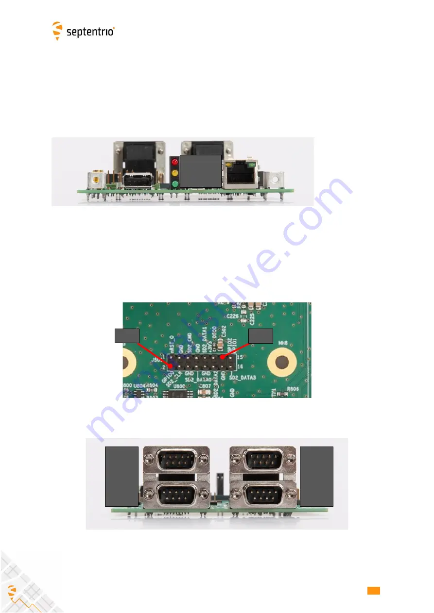
The POWER LED lights when the DevKit is powered.
The GPLED and LOGLED are connected to the homonymous pins of the 30-pin connector
of the AsteRx-m3 board. See section 2.5.1 for the pinout, and Appendix A for a description
of the LED behavior.
The 3.3V GP1 and GP2 outputs are available on the J501 header.
4.5
COM Ports
By default, the four COM ports of the AsteRx-m3 are routed to the four DB9 connectors.
Electrical levels on the BD9 conform to the RS232 standard. RTS/CTS lines are supported
only on COM2 and COM3. Connection to a PC is done through a null-modem cable.
- POWER
- GPLED
- LOGLED
COM 1
COM 2
COM 3
COM 4
GP1
GP2


