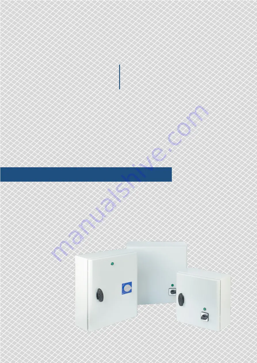
Mounting and operating instructions
STANDARD 230 VAC
TRANSFORMER CONTROLLER
POWER RANGE: 10,0—20,0 A
STR-1
Page 1: ...Mounting and operating instructions STANDARD 230 VAC TRANSFORMER CONTROLLER POWER RANGE 10 0 20 0 A STR 1 ...
Page 2: ...UCT DESCRIPTION 4 ARTICLE CODES 4 INTENDED AREA OF USE 4 TECHNICAL DATA 4 STANDARDS 4 OPERATIONAL DIAGRAM 5 WIRING AND CONNECTIONS 5 MOUNTING INSTRUCTIONS IN STEPS 5 VERIFICATION OF INSTALLATION 7 TRANSPORT AND STORAGE 8 WARRANTY AND RESTRICTIONS 8 MAINTENANCE 8 STANDARD 230 VAC TRANSFORMER CONTROLLER STR 1 ...
Page 3: ...ironment is as dry as possible avoid condensation All installations shall comply with local health and safety regulations and local electrical standards and approved codes This product can only be installed by an engineer or a technician who has expert knowledge of the product and safety precautions Avoid contacts with energised electrical parts Always disconnect the power supply before connecting...
Page 4: ...STR 1160L20 16 0 F T 25 0 A H STR 1200L20 20 0 F T 30 0 A H INTENDED AREA OF USE Speed control of voltage controllable 230 VAC single phase motors For indoor use only TECHNICAL DATA Supply voltage 230 VAC 50 60 Hz Maximum motor current depends on the version see article codes Unregulated output 230 VAC Wide power range 5 step rotary switch for manual control plus off position LED status indication...
Page 5: ...ions and follow these steps Choose a smooth solid surface for installation a wall panel etc Follow these steps 1 Open the door of the controller Mind the wires that connect the rotary switch with the autotransformer or with the printed circuit board depending on the product version 2 Mount the enclosure using corrosion resistant screws or bolts Mind the correct mounting position and unit mounting ...
Page 6: ...Incorrect 50 mm 50 mm 75 mm 50 mm 1 3 2 4 Article code A mm B mm C mm D mm E mm STR 1100L22 300 325 185 255 255 STR 1130L22 300 325 185 255 255 STR 1160L20 300 425 235 255 355 STR 1200L20 300 430 235 255 355 6 Insert the cables through the cable glands and do the wiring according to the wiring diagram see Fig 3 while adhering to the information from section Wiring and connections above 6 1 Connect...
Page 7: ...0 110 140 170 190 230 Unregulated output VAC L1 0 230 230 230 230 230 230 Available but not connected VERIFICATION OF INSTALLATION ATTENTION Use only tools and equipment with non conducting handles when working on electrical devices After connecting the unit to the mains supply the green LED on its cover should light up indicating that the controller is supplied Safe operation depends on proper in...
Page 8: ... alterations to the product after the date of publication relieve the manufacturer of any responsibilities The manufacturer bears no responsibility for any misprints or mistakes in this data MAINTENANCE In normal conditions this product is maintenance free If soiled clean with a dry or damp cloth In case of heavy pollution clean with a non aggressive product In these circumstances the unit should ...