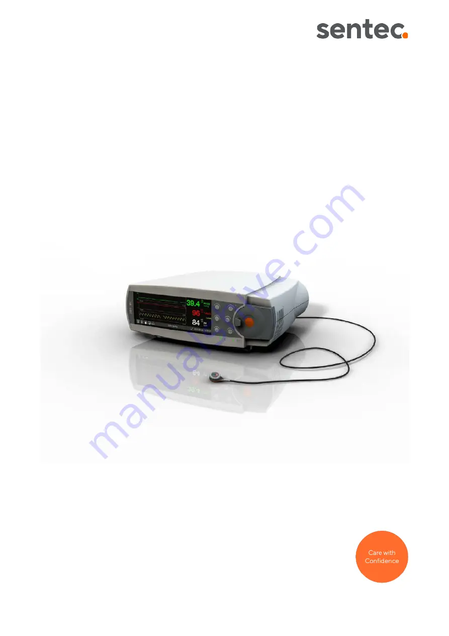
Sentec Digital
Monitoring System
Installation at Home User Site by
Instructed Personnel
Page 1: ...Sentec Digital Monitoring System Installation at Home User Site by Instructed Personnel ...
Page 2: ...e power cords provided by Sentec Note Mains cables are country specific and may differ in shape and or color This manual provides systematic guidance for an instructed person from a homecare provider on setting up the SDMS at the patient s home site The SDMS shall only be used if all of the following steps have been carried out successfully Note Installation of the SDMS including configuration of ...
Page 3: ...nt or strangulation To make no changes to the device setup For switching off and uninstalling the SDMS and disconnecting the Isolation Transformer see section 2 4 For ensuring maintenance see section 3 Note The patient as lay operator cannot modify the SDM s configuration by using the SDM s menu If the SDMS has been stored below 10 C 50 F it must be acclimatized for two hours at room temperature b...
Page 4: ...t is to be used Interference from interventional devices The SDM is protected against electrostatic defibrillator discharge Parameter display may be temporarily affected during electrostatic discharge defibrillation but will rapidly recover Nevertheless during electro surgery the SDM sensor and cables are to be physically separated from the electro surgical equipment The sensor must not be placed ...
Page 5: ...y or on purpose Either select the preconfigured SDM Home Profile of V STATS or follow the below steps 1 Switch off auditory alarm signals permanently using V STATS 2 Set the patient s individual measurement parameters 3 Then select System Settings Display in Sleep Mode 4 Disable patient menu access by unticking the Menu Access box within the V STATS system settings For further information refer to...
Page 6: ... 0 84 A 0 44 A Frequency 50 60 Hz 50 60 Hz Output 100 VA 100 VA Energy efficiency 94 94 Earth leak current 100 μA 127V 100 μA 254V Overheating Protection 120 C 248 F 120 C 248 F Isolation class ta 40 B ta 40 B Protection class plugs IP 20 IP 20 Protection class transformer IP 42 IP 42 Dimensions LxWxH ca 160 x 126 x 73 mm 160 x 126 x 73 mm Storage temperature 10 C to 50 C 14 F to 122 F 10 C to 50 ...
Page 7: ...mer if the housing or cables are damaged Do not throw or drop the Isolation Transformer This may damage the inside of the unit Never connect the SDM mains cable to multiple socket outlets or extension cords The Isolation Transformer is only to be used below 2000 m a s l 80 kPa 1 Place Isolation Transformer horizontally on the floor Make sure the SDM mains cable is disconnected from mains and from ...
Page 8: ...h responds at approx 120 C and switches off the transformer The overheat protection is self resetting and will only switch on the transformer again when it has cooled down Simplified depiction of final SDM Isolation Transformer assembly Instructed personnel from the homecare provider shall electrically test the Isolation Transformer at least every 6 months chapter 3 1 Refer to the Instruction Manu...
Page 9: ... HB 010103 e Date of release 01 2022 9 2 4 Disconnecting the Isolation Transformer from SDM 1 Disconnect mains supply plug from the wall socket 2 Open the Water Protection Box remove and disconnect the cables C13 C14 3 Disconnect the isolation transformer from the SDM ...
Page 10: ...P N up to 36 months OxiVenT Sensor OV A P N 12 months 1 The average amount of time that an item is estimated to function when installed new assuming correct diligent handling and routine maintenance is practiced For the avoidance of doubt the indicated expected useful lifetime is for information purposes only and as such does not constitute imply or establish any warranty or guarantee Shelf Life o...
Page 11: ...tral shortened as well as secondary live neutral shortened Measure primary vs secondary primary vs protective earth secondary vs protective earth The insulation resistance shall not be below 100 MΩ Earth leakage currents Device under test must be in normal operating condition The current shall be measured with the mains polarity normal and reversed Measure current from secondary live and neutral s...
Page 12: ...oubt please contact a qualified electrician or your local Sentec representative 2 Socket Wiring Test Check the socket for verification of proper electrical wiring Verify no wire is missing Verify live neutral are connected to L N terminals may be inverted Verify protective earth is connected to the PE terminal N PE must not be inverted Voltage between protective earth and neutral shall not exceed ...
Page 13: ... example may be used to verify proper socket installation and wiring The below example may be substituted by other products For further information refer to the respective socket tester s Instructions for Use Plug Type Rated operating voltage Brand Name Socket Tester Manufacturer F E CEE 7 7 Compatible to Schuko plug 230 V AC 50Hz Voltcraft VC40 Conrad Electronic International GmbH Co KG www conra...
Page 14: ...dicates that the instruction manual must be read Consult instructions for use Indicates the need for the user to consult the instructions for use IP XY IP class of device Degree of ingress protection X Protection against solids Y Protection against liquids CE mark Indicates that the product complies with the requirements of the Medical Device Directive 93 42 EEC June 1993 or Medical Device Regulat...
Page 15: ...ort circuits Defibrillation Proof Type BF Degree of protection against electrical shock Defibrillation proof Type BF applied part Temperature limit Indicates the temperature limits to which the medical device can be safely exposed Fragile handle with care Indicates a medical device that can be broken or damaged if not handled carefully Keep dry Indicates a medical device that needs to be protected...
Page 16: ...Sentec AG Ringstrasse 39 CH 4106 Therwil Switzerland www sentec com HB 010103 e Date of release 01 2022 16 ...