MX-7000 Installation and operation manual
P a g e
| 15
Connecting the MX-7000
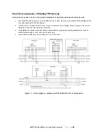
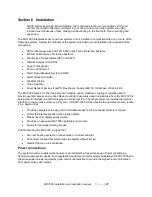
1. Refer to Section 6 for installation details for the MX-7000 unit. Connect the MX-7000 to its
power supply transformer and battery pack as shown in Figure 21. Apply power to the MX-
7000 by connecting the AC power first, and then the battery pack.
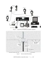
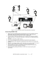
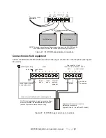
2. Connect the FPS/MPS MX copper transponder loop cable to the MX-7000 rear panel as
shown in Figure 6 and Figure 22. If there are multiple loops, connect each to the appropriate
MX loop card.
3. Enter setup, acknowledge all alarms and perform the MX-7000 initial configuration.
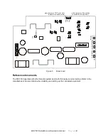
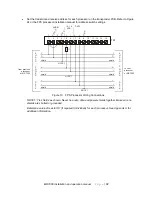
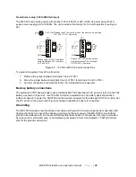
4. Each FPS2-2M field processor supply voltage must be between 12-16 VDC. If the end of line
processor supply voltage is below 12 VDC, the MX-7000 copper loop card output voltage at
TB1, pins 4, 5 (see Figure 20) can be increased by trimming R40 on the loop card. If the end
of line processor supply voltage cannot be brought to 12 VDC without exceeding 16 VDC at
the first in line processor then voltage dropping supply resistors must be added as described
in appendix A.
5. Complete the MX-7000 configuration by performing the steps required for your system (see
Section 7).
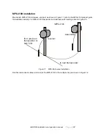
6. Adjust the count and gain switches on each FPS processor to provide the required climb and
cut detection. Align each MPS-4100 microwave pair to optimize the detection zones.
7. Perform detection and nuisance alarm testing in each zone and perform fence quieting
procedures and microwave re-alignment if necessary.
8. Perform final testing, including the climb test, in each zone as required by the system
specifications.


