


Perimeter layout guidelines
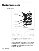
4 - 8 • • • Intelli-FLEX II product guide
Perimeter layout guidelines
Once the existing site features (i.e., fences) have been adapted to meet
specifications, the perimeter must be laid out. Layout guidelines for each
Intelli-FLEX II component are detailed in this section. These guidelines will
provide you with the information that you require to layout an effective
Intelli-FLEX II system.
Use a site plan to mark the locations for the Intelli-FLEX II components as follows:
•
sensor cables - indicate layout of cable in each zone
Senstar strongly recommends installing the sensor
cables on the secure side of the perimeter (the side of
the fence opposite the threat).
•
non-sensitive feed cable - indicate layout of cable in each zone
•
Intelli-FLEX II dual zone processors
•
optional equipment
•
cable connectors - indicate type of connector (splice, terminator)
•
power supply - indicate type of power supply and power distribution plan
•
communications system wiring plan
Cable layout guidelines
This section provides the information required to determine the amount of cable
required to install your Intelli-FLEX II system. Installation guidelines are found in
Chapter 5, Installation instructions
. Keep the following in mind when
determining your cable requirements:
•
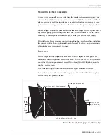
The sensor cable must be mounted on the same or similar type of surface for
each zone. (i.e., one type of fence) DO NOT install one sensor cable on both
fence fabric and barbed wire.
Figure 4-4 Fence type installation rule
NEVER install a sensor cable on
both fence fabric AND barbed wire.
Use two separate sensor cables.
One on the fence fabric, and
one on the barbed wire.


