


Installing the sensor cable
FlexZone Product Guide
Page 37
Cable preparation (all connections)
1. Cut the sensor cable to the correct length for the application:
•
For splice connections, cut the sensor cable 15 cm (6 in.) past the specified location of the
splice.
•
For terminations, cut the cable 0.5 m (20 in.) past the specified termination point.
•
For processor connections, pull approximately 60 cm (2 ft.) of sensor cable into the
enclosure through the two cable glands on the right side of the enclosure.
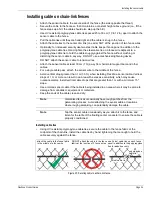
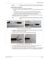
2. Carefully, remove 20 mm (0.8 in.) of the outer jacket and the mylar film from the end of the
sensor cable. DO NOT nick the braided shield.
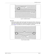
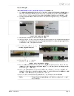
3. Separate the strands of the exposed braided shield, and twist the strands into two separate
conductors, on opposite sides of the cable.
4. Peel back and remove the foil covering flush with the black outer jacket.
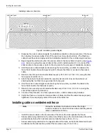
5. Trim back the clear tube to a length of 5 mm (1/5 in.) by carefully removing app. 15 mm
(3/5 in.) from the end of the cable. DO NOT nick the center conductor.
6. Bend and form the two sections of twisted braided shield into conductors that are parallel with,
and separated from, the center conductor by 5 mm (1/5 in.) on opposite sides of the cable.
Note
Keep the sensor cable and enclosure clean and dry during installation.
TIP
Cut only part way into the outer jacket and then twist the two sections
apart.
Figure 34: Preparing FlexZone sensor cable step 2
Figure 35: Preparing FlexZone sensor cable steps 3 & 4


