


Replacing the processor/battery
FlexPS Product Guide
Page 81
Using the Power Grid filters
Some sites have an extremely high level of EMI at certain frequencies, which can lead to an
increase in the FlexPS false alarm rate (FAR). This has been known to occur at electrical
generating stations, electrical transformer stations and solar power farms. To counter the effects of
high EMI, FlexPS includes two selectable low frequency filters that can be used to screen out 50
Hz and 60 Hz noise. The following procedure can be used to determine if such a condition exists
at your site and to correct the situation if it does exist. The main symptom of this problem is false
alarms for which the source of the alarms cannot be identified.
1.
Connect the UCM computer directly to the suspect processor and establish a connection.
2.
Open the Config window and select the Calibrate button.
3.
Start recording a Frequency Response plot and look for noise spikes at the 50 or 60 Hz
frequencies.
4.
If noise spies are present at either frequency, select the corresponding Power Grid filter (50 Hz
or 60 Hz).
5.
Continue monitoring the processor the verify that false alarms are not being caused by noise
spikes.
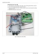
Replacing the processor/battery
The processor PCB is mounted on a backplate. It is secured inside the enclosure by two tabs that
fit into the slots on the bottom of the backplate and by the locking tab that latches over the top of
the backplate. The battery fits into a compartment below the PCB assembly (see
Removing the processor assembly
1.
Label and disconnect the removable terminal blocks.
2.
Disconnect the PCB ground strap, the tamper switch connector, and if required, the battery
harness connector.
3.
Push the tamper switch mounting bracket away from the PCB until the locking tab is clear of
the backplate.
4.
Hold the tamper switch mounting bracket away from the PCB and lift the backplate/PCB
assembly off the two tabs and out of the enclosure.
Replacing the battery
5.
Remove the battery from its compartment.
6.
Disconnect the battery harness from the battery.
7.
Connect the battery harness to the replacement battery (observe polarity).
8.
Replace the battery in the compartment.
Note
A direct USB connection is required to use the Frequency Plot mode on
the Calibrate tool.
CAUTION
The processor PCB includes static sensitive components. Follow
proper ESD handling procedures when working on the PCB.
Note
Do not remove the processor PCB from the backplate.