


FlexPS initial calibration
FlexPS Product Guide
Page 71
Testing the fence condition
To determine if there are any loose fittings or parts of the fence that can cause nuisance alarms in
windy weather, grip a fence panel in the middle and gently push and pull on the fence with an
increasing motion. Run a UCM magnitude response plot and listen for any metal on metal contact
while conducting the shake test. When you review the plot, look for any response spikes that are
over the threshold. If the shake test causes metal on metal contact, or generates response spikes
over the threshold, locate and correct the problems on the fence. This will help to prevent nuisance
alarms during inclement weather.
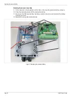
Connecting the UCM via USB
1.
Remove the enclosure cover and connect the UCM computer to the processor via USB (T3).
2.
Start the UCM software (the UCM Connect dialog displays).
3.
Select Connect to establish a connection to the processor.
(e.g., Network Type: = Silver Network; Device Type = FlexPS; Address = 1 {default address};
select USB radio button; USB Device = processor ID).
The FlexPS Status window opens.
Sensor calibration
FlexPS calibration is done under the Config tab. Select the Config tab and the Cable Configuration
window displays.
The Calibrate tool
The Calibrate tool is provided to assist you in adjusting the processor’s Gain and Filter Settings.
Use the Calibrate tool to see the effects of Cable gain, Audio gain, and Filter adjustments before
changing the processor’s settings. First, make the configuration changes using the calibrate tool.
You can then view a magnitude or frequency response plot of the new settings while testing the
installation. If the configuration changes do not result in the required level of detection, you can
continue making and reviewing adjustments. When you are satisfied with the results, you can
download the new parameters to the processor.
Adjusting the Cable setting
The Cable setting amplifies the signal received from the sensor cable before it is processed. There
are 8 distinct cable gain settings ranging from 1, the lowest gain, to 8, the maximum. Begin with
the default Cable setting of 2. Next, open the Calibrate tool and test the processor’s response.
Finally, adjust the Cable setting, if required, and then retest the response.
1.
Under the Cable Cfig tab, verify that the Cable setting is at the default value of 2.
2.
Open the Calibrate tool, and setup the tool by selecting the Cable side (A or B) and
Magnitude.
Note
Ensure that the correct Cable Type is selected for each cable side,
before adjusting the Gain.
Note
Although the Cable setting amplifies the received signal it also
amplifies the ambient fence noise. Use care when adjusting the
processor’s Cable setting.
Note
The sensor cable response is affected for approximately 4 seconds
after each alarm while the filters clear.