


Installation recommendations
Page 28
FP400 Product Guide
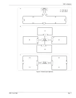
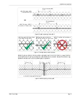
For a double swinging gate, both gate panels are protected by sensor cable.
Determining cable length requirements for gates
1.
For each gate panel:
•
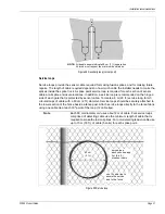
The sensor cable passes around the circumference of each gate panel at ¼ the gate
height, 30 cm in from the outside edge, and ¾ the gate height.
length of cable to protect a gate = 2 X (gate length - 30 cm) + gate 2 X (distance
from inside edge of gate to fence post) + (60 cm for sensitivity loop) + optional service loop
2.
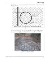
To reach the other side of a gate:
•
Create a sensitivity loop beside the fence post adjacent to the gate. Run the sensitivity
loop up 30 cm and back down the post to pass through the split conduit. Loop the cable
around the gate as described in step 1. Pull the cable through the conduit to the other side
of the gate. The conduit should be buried at least 30 cm deep, and the conduit ends
should be at least 30 cm above ground level. Seal both ends of the conduit (water tight).
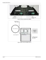
Using the cable management kit at the hinged side of protected gates
The cable management is used at gate locations to protect the sensor cable from binding or being
pinched by the gate while allowing the cable to rotate freely when the gate is opening and closing.
The split conduit is fitted against the fence post on the hinged side of the gate so that it is
perpendicular to the fence line. Two gear clamps are used to secure the conduit to the fence post.
The conduit must have notches cut at points where gate hardware is attached to the post, so the
conduit can fit snugly and flush against the fence post.
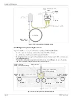
Figure 22 Cable layout on a single panel swinging gate
Figure 23 Double panel swinging gate
conduit
cable management kit
3/4 fence height
1/4 fence height
service loop
all turns must respect the minimum bend radius
seal conduit
ends
30 cm
conduit
FPKT0500
1/4 fence height
3/4 fence height
all turns must respect the minimum bend radius
30 cm (1 ft.)