


D11-044-1: Rapidox 1100ZR-H-OL-LC O
2
Analyser Instruction Manual
D11-044-1
22
Last printed 08/11/2016 12:10:00
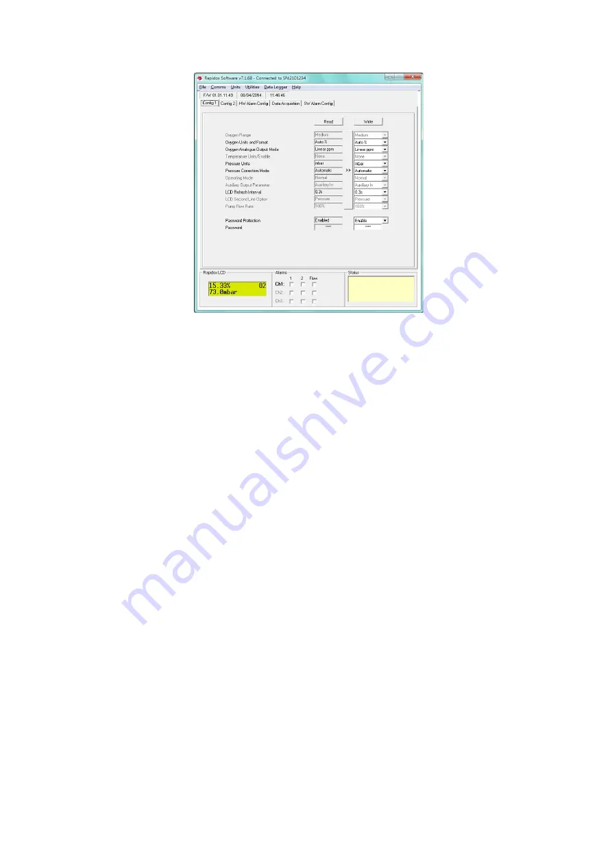
Figure 9: Rapidox configuration page. Note the actual values used may differ from those shown
above.
The yellow status box at the bottom will display confirmation that the Rapidox
was found and the result of the last action, or any error messages if there is a
problem with communication. If you experience problems check that your serial
cable (supplied) is correctly fitted to a valid serial port. Also check the status of
your COM port settings in Device Manager accessed by clicking START – Settings
- Control Panel.
6.3
On-Screen Help
You can access the on-screen help facility at any time by clicking on the help
menu on the menu bar and select the ‘Help’ option or press F1.
6.4
Configuration Page
The configuration page is split into three, and you can switch between them by
clicking on the tabs labelled “Config 1”, “Config 2” or “Alarm Config”. Each page
allows the user to reprogramme an array of variables used by the Rapidox. Once
written to the Rapidox, the new variables remain permanent until overwritten.
To read the current configuration stored in your Rapidox select ‘Read Analyser
Configuration’ from the ‘File’ menu, or click the ‘Read’ button on any of the
‘Config’ pages. Note that the entries in the boxes on the RHS (under the ‘Write’
button) will turn red if the value is different to that just read and a red asterisk
will appear next to the ‘Write’ button to warn you that a change has been made.
The left-hand set of grey text fields (‘read fields’) will be updated with the current
configuration data. To save this information (e.g., if several people share the same
instrument) click the long copy (‘>>’) button (between the ‘Read’ and ‘Write’