background image


Appendix B: GPR Emissions, Interference and Regulations 


73 


Appendix B: GPR Emissions, Interference and 
Regulations  


All governments have regulations on the level of electromagnetic emissions that an electronic 
apparatus can emit.  The objective is to assure that one apparatus or device does not interfere 
with any other apparatus or device in such a way as to make the other apparatus non-
functional.  


The manufacturer test their GPR products using independent professional testing houses and 
comply with latest regulations of the USA, Canada, European Community, and other major 
jurisdictions on the matter of emissions. 


Electronic devices have not always been designed for proper immunity.  If a GPR instrument is 
placed in close proximity to an electronic device, interference may occur.  While there have 
been no substantiated reports of interference to date, if any unusual behavior is observed on 
nearby devices, test if the disturbance starts and stops when the GPR instrument is turned on 
and off.  If interference is confirmed, stop using the GPR.  


Where specific jurisdictions have specific GPR guidelines, these are described below. 


B-1  FCC Regulations 

This device complies with Part 15 of the USA Federal Communications Commission (FCC) 
Rules.  Operation in the USA is subject to the following two conditions:


this device may not cause harmful interference and 
 
this device must accept any interference received, including interference that may cause 
undesired operation. 

Part 15 

– User Information


This equipment has been tested and found to comply with the limits for a Class A digital device, 
where applicable, and for an ultra-wide bandwidth (UWB) device where applicable, pursuant to 
Part 15 of the FCC Rules. These limits are designed to provide reasonable protection against 
harmful interference when the equipment is operated in a commercial environment. This 
equipment uses and can radiate radio frequency energy and, if not installed and used in 
accordance with the instruction manual, may cause harmful interference to radio 
communications. Operation of this equipment in a residential area is likely to cause harmful 
interference in which case the user will be required to correct the interference at his/her own 
expense. 

WARNING


Changes or Modifications not expressly approved by the manufacturer could voi

d the user’s 

authority to operate the equipment.


Certification of this equipment has been carried out using approved cables and peripheral 
devices.  The use of non-approved or modified cables and peripheral devices constitutes a 
Change or Modification outlined in the warning above.


Operating Restrictions


Operation of this device is limited to purposes associated with law enforcement, firefighting, 
emergency rescue, scientific research, commercial mining, or construction. Parties operating 
this equipment must be eligible for licensing under the provisions of Part 90 of this chapter. 


Summary of Contents for LMX100

Page 1: ...2016 00048 05 ...

Page 2: ...ii ...

Page 3: ...e fax it to 1 905 624 9365 or register your product online at www sensoft ca product registration Name Company Name Address City State Province Zip Code Country email Phone Fax Component Serial Numbers refer to packing list or the sticker on the component Comp Serial Comp Serial Comp Serial Comp Serial Comp Serial Comp Serial Comp Serial Comp Serial Comp Serial Comp Serial Vendor Name Date Receive...

Page 4: ...Product Registration iv ...

Page 5: ...sors Software Inc retains worldwide title and rights to all its software and that the SOFTWARE PRODUCT contains proprietary materials protected under copyright trademark and trade secret laws Grant of Software Product License In consideration of payment of the license fee which is the price you pay for the SOFTWARE PRODUCT and your agreement to abide by the terms and conditions of this License Agr...

Page 6: ...eteness is not guaranteed Before using this product you must evaluate it and determine if it is suitable for your intended application You assume all risks and liability associated with such use Any statements related to the product which are not contained in Sensors Software Inc current publications or any contrary statements contained on your purchase order shall have no force or effect unless e...

Page 7: ... apply to you General No right license or interest to any Sensors Software Inc trademarks is granted hereunder with the purchase of the PRODUCT or the SOFTWARE PRODUCT license Governing Law In the event of any conflict between any provision in this license agreement and limited warranty and any applicable provincial legislation the applicable provincial legislation takes precedence over the contra...

Page 8: ...are Inc 1040 Stacey Court Mississauga Ontario Canada L4W 2X8 Tel 905 624 8909 Toll Free 1 800 267 6013 Fax 905 624 9365 Email customerservice sensoft ca Sensors Software Inc trademarks are listed at www sensoft ca trademarks 1999 00236 04 ...

Page 9: ...e battery charger AC adapter The battery charger AC adapter is rated for indoors use only Do not replace detachable MAINS supply cords for the battery charger AC adapter by inadequately RATED cords Do not position the Display Unit such that it is difficult to disconnect the 37 pin GPR connector The exterior of this product should be cleaned using a damp cloth Safety Symbols Consult this documentat...

Page 10: ...x ...

Page 11: ... 1 9 GPR Plot Options 18 4 1 10 Reset to Defaults 19 4 2 System Test 20 4 2 1 System Information 20 4 2 2 Keypad Test 21 4 2 3 Audio 22 4 2 4 Touch Screen 22 4 2 5 Sensor Test 23 4 2 6 Odometer Calibration 24 4 2 7 GPS 26 5 GPR Concepts 29 5 1 Theory 29 5 2 Hyperbolas 29 5 3 Calculating Depth 30 5 4 Soil Calibration Values 30 5 5 Air Waves 31 6 Data Collection 33 6 1 Acquiring Data 33 6 1 1 DynaQ ...

Page 12: ...it Problem 58 9 5 Wobbly Wheels 58 9 6 Creating a Test Line for Data Quality 58 9 7 Contacting the Vendor for Service 58 10 Care Maintenance 61 10 1 Battery Care 61 10 2 Cable Care 61 10 3 Skid Pads 62 10 4 Odometer 62 10 5 Storage Cases 62 10 6 Upgrading Embedded Software on Display Unit 62 11 Parts List Accessories 65 11 1 Spare Parts 65 11 2 Accessories 67 12 Technical Specifications 69 Appendi...

Page 13: ...ferencing data Ability to draw arrows on the screen to highlight objects Easy screen captures of data This manual describes everything you need to assemble the system change settings and start scanning There is also a section that describes the basics of GPR theory and techniques for locating utilities This manual references embedded software version V1 R6 To see which software version is installe...

Page 14: ...Overview 2 ...

Page 15: ... 1 Out of the box You will find the following components in your LMX100 box Some of these may already be assembled Attach the Cart Handle to Cart Base using the Handle Pins Ensure the Display Unit Tray is facing the operator ...

Page 16: ...splay Unit onto the Display Unit Tray on the Cart The Display unit slides down into the tray catching on both sides of the mount and is held in place with the pull pin When a click is heard the Display Unit is firmly in place Adjust the angle of the Display Unit by loosening the hand screws underneath the Display Unit Tray rotating the Display Unit to the desired angle and tightening the hand scre...

Page 17: ...ter and Battery Cables The Odometer Cable connects to the closest receptacle on the Sensor Attach the Battery Cable to the Sensor and the Battery The system is now setup and ready to use Odometer Cable Battery Cable Display Cable ...

Page 18: ...Assembly 6 2 2 Fully Assembled The fully assembled LMX100 will look like the following Simply reverse directions to disassemble for transport ...

Page 19: ...e the colour of the LED will indicate the amount of battery power remaining 20 to 100 green 10 to 20 orange 0 to 10 red The first time you turn on the LMX100 you will need to configure the system Figure 3 1 A series of screen prompts will allow you to setup the language units date time and some other options You will have to do this again anytime you update the embedded software Section 10 6 Every...

Page 20: ...d by the Display Unit The Display Unit has embedded software to set survey parameters and collect display and store data The Display Unit offers touch screen operation as well as a water resistant membrane keypad with a number of buttons that can be pressed to perform various tasks Most operations can be done using either the touch screen or the keypad Use the following table as a guide to working...

Page 21: ... to display a Swipe Down menu Figure 3 3 with the following items Date and Time The current date and time 12 hour clock The time needs to be changed in areas that observe daylight savings time Battery The battery icon displays the amount of power remaining in the battery GPS Shows the status of the GPS receiver Wi Fi Network Indicates if the system is connected to a wireless network and if so the ...

Page 22: ... used to increase and decrease the screen brightness Increasing the brightness setting may improve the visibility of the screen in bright sunlight Note however that increasing the screen brightness also increases power consumption thus reducing battery life To close the Swipe Down menu touch anywhere on the screen below the swipe down menu ...

Page 23: ...enu Here you can set preferences adjust system settings and perform system tests You will see the screen shown in Figure 4 1 Figure 4 1 Tools menu 4 1 Preferences Selecting the preferences option will take you to the sub menu shown in Figure 4 2 Figure 4 2 Setting Preferences ...

Page 24: ... Region is displayed Press the and buttons on either side of the displayed Country Region to alphabetically move to the next or previous country or region Alternatively both Language and Country Region can be changed by pressing the and buttons on the bottom of the screen Press Back when you are done Figure 4 3 Changing Language and Country Region 4 1 2 Units Pressing Units will cycle between US S...

Page 25: ... hotels and airports that require a web based login and acceptance of their Terms Conditions It also CANNOT connect to unsecured networks networks that do not require a password If you are already connected to a Wi Fi network the name of the network is listed beside the Wi Fi Network field Selecting Wi Fi Settings takes you to a sub menu Figure 4 4 for connecting and configuring Wi Fi settings Fig...

Page 26: ... connected to that network o Scan Scans for any available networks in the area and displays them in order of strength of signal You may need to press this button a second time if you don t see the network you are looking for o Details Pressing this button displays the security settings and device addresses related to the selected network o Back Press this button to return to the System Settings sc...

Page 27: ... are no warning messages the email address is setup properly and you are ready to email mini reports from the field If this does not work see the Failed Setup section below Using Another Provider Note It is highly recommended to use a GMAIL account as the system is pre configured for this If you choose to use another provider you will have to contact that provider if you have any issues with the s...

Page 28: ...e for SMTP host name provider where provider is the host name e g Yahoo or AOL Press OK when done Press Server Port to display a keyboard where you can enter the port number used by the email server Searching online for host name will usually provide the port number for that email provider In most cases it s usually 465 if SSL is enabled see next bullet point or 587 See chart below for some exampl...

Page 29: ...ess or password was entered incorrectly try re entering these fields 2 Hostname port or SSL setting are incorrect 3 Your email security settings may need to be adjusted which may require you to login to your email account from a PC or mobile device An example of the GMAIL security settings is shown below current as of writing this manual For other email providers you may need to modify the setting...

Page 30: ...reen Saver can be set to turn the screen off after 1 minute 5 minutes or never OFF setting Pressing this button cycles between those three options When the screensaver is activated and the screen shuts off touch anywhere on the screen to turn it back on again 4 1 9 GPR Plot Options Selecting this option will display the screen in Figure 4 8 ...

Page 31: ...1 10 Reset to Defaults Selecting this option at the bottom of the screen will reset all settings preferences back to the default settings Figure 4 9 Pressing this will ask you to confirm the Reset to Defaults If Yes is selected the next screen will ask if you would like to remove all saved wireless networks and emails addresses Note that any saved screenshots will still remain on the system Figure...

Page 32: ... or failed the test Each test is described below in more detail Figure 4 10 System Test menu 4 2 1 System Information System Information is the only option in System Test which is not actually a test Here information such as the version serial numbers temperature and battery power are displayed Figure 4 11 There are two options at the bottom of this screen Export If a USB key is currently inserted...

Page 33: ...tware This is to help with gathering information about any system irregularities As the name suggests the notification is completely anonymous and no personal information is sent 4 2 2 Keypad Test The keypad test ensures that all buttons on the membrane keypad are working Press Start to begin the test which requires the user to press each button once within a 20 second timeframe Figure 4 12 Figure...

Page 34: ...hould hear a sound with an increasing pitch Figure 4 13 Audio Test 4 2 4 Touch Screen The test checks proper operation of the touch screen Figure 4 14 It allows you to test the screen by pressing Test or perform a quick calibration followed by a test by pressing Calibrate Both involve touching targets on the screen in the allotted time Figure 4 14 Touch Screen test on the left Touch Screen calibra...

Page 35: ...oper operation of the GPR sensor including the amplitude of the pulse Once the cart is tipped backwards and start is pressed it will conduct the test Figure 4 15 If there are any irregularities the test will indicate failure Figure 4 15 Sensor Test ...

Page 36: ...screen in Figure 4 16 The following options exist Figure 4 16 Screen displaying current odometer calibration Odometer Test This test verifies the odometer is calibrated properly It involves moving the system a set distance 5m or 10 depending on units used and comparing the value obtained to a known value The screen in Figure 4 17 will be displayed once Odometer Test is pressed Press Start to begin...

Page 37: ...ight Odometer Calibration This option actually calibrates the odometer Figure 4 19 Choose a set distance from the screen or select Custom Then press Start and move the system that exact distance using a measuring tape or other known distance indicator Press Finish when you have travelled that distance ...

Page 38: ...0 right image The odometer calibration value is stored in the Display Unit If the Display Unit is changed or swapped out you will need to run the Odometer Calibration test again Figure 4 20 Results of successful Odometer Calibration Left Image on Right shows a failure as calibration is out of range 4 2 7 GPS The internal GPS can be used to geo reference screenshots so they can be positioned on Goo...

Page 39: ... being applied such as DGPS Pressing Strings will display the raw data strings that are outputted by the GPS Figure 4 22 as they scroll down the screen The user may select this option to verify the GPS is outputting the proper NMEA string format Figure 4 22 GPS Strings Pressing Clear will clear the strings Pressing Info will return to the main GPS test menu ...

Page 40: ...Tools 28 ...

Page 41: ...Hyperbolas The GPR display shows signal amplitude versus depth time and sensor position along a line Since radar energy radiates in a 3D cone shape rather than a thin beam a hyperbola or inverted U is the GPR response from a small point target like a pipe rock or a tree root The radar wave hits the object before and after going over it and forms a hyperbolic reflection that can appear on the recor...

Page 42: ...𝑎𝑦 𝑡𝑟𝑎𝑣𝑒𝑙 𝑡𝑖𝑚𝑒 For the LMX100 velocity is indicated by the Soil Calibration Value known as Soil Cal Once the Soil Cal values are set the measured depths will be determined accurately Section 6 2 4 5 4 Soil Calibration Values Below is a table of common subsurface materials and their corresponding Soil Cal This is only a guideline and there is some variation based on the fact that there can be a mix...

Page 43: ...ays how air wave reflections affect data An important part of understanding the data image is learning to recognize these unwanted air targets and distinguish them from the targets in the ground Good field notes are indispensable for helping identify unwanted events on the data The best way to identify air reflections is the target hyperbola method Hyperbolas from above ground objects are wider th...

Page 44: ...GPR Concepts 32 ...

Page 45: ...S Status Indicator lower left in Figure 6 1 shows the quality of the GPS signal which is based on the number of satellites that it sees The chart below explains what the colours and bars mean Indicator Color of bars of Satellites Red 1 4 Orange 2 5 Green 3 6 7 Green 4 8 9 Green 5 10 6 1 Acquiring Data The system is ready to collect data as soon as you see this screen As the system is pushed along ...

Page 46: ...em movement speed varies In most situations moving the system at a comfortable walking speed generates data of good quality In situations where target resolution or maximum penetration depth is critical moving slower increases data quality As the Line Scan data scrolls on the screen the DynaQ Index Bar is displayed along the bottom of the screen Figure 6 2 The color of the bar indicates the qualit...

Page 47: ... down by dragging the horizontal line to the desired location Figure 6 3b Alternatively you can also use the Up and Down arrows on the 4 way directional keypad Note make sure you have done a Soil Calibration to ensure depth accuracy Section 6 2 4 Figure 6 3 a Back up Indicator b Moving the Depth Indicator to the top of the hyperbola To locate a feature simply roll the system back along the same pa...

Page 48: ...el lines over a target and show all the passes on the screen for comparison Once you collect some data press Pause You can now move the LMX100 without data scrolling on the screen When you are ready to resume collecting data press Resume You will see a thick red vertical line corresponding to when you hit the Pause button and then restarted While in Pause mode press the Exit button to exit data co...

Page 49: ...rt a vertical arrow pointing up at that position In the example in Figure 6 6 the user touched near the hyperbolas then swept their finger towards the top to create the arrows Touch any arrow to remove it Figure 6 6 Drawing arrows on the screen to highlight features 6 1 6 Flags Flags are often inserted to mark noteworthy surface features such as poles sidewalks changes in terrain etc These markers...

Page 50: ...View Settings button will change the menu at the bottom of the screen so the user can adjust the way data is viewed on the screen Figure 6 8 This can be useful for optimizing the appearance of different features Figure 6 8 Pressing LineView Settings changes the bottom menu on the screen ...

Page 51: ...6 2 2 Filter The Filter is a background subtraction filter used for removing flat lying responses in the data Filtering helps identify shallow targets that might be masked by the strong signals at the top of the image as well as possibly enhancing the visibility of hyperbolas further down in the data However it will also filter out other flat lying responses such as soil boundaries so be careful w...

Page 52: ...ay depth of the data This is commonly referred to as the depth window The pre set values range from 1m to 8m 4 to 30 see Figure 6 11 If the data was collected with a shallower depth the depth setting can still be increased after the fact when reviewing the data In general it s a good idea to set your displayed depth to 1 5 2 times the depth you expect the deepest target to be Position Pressing and...

Page 53: ...Data Collection 41 Figure 6 11 Varying displayed depth Figure 6 12 Varying position or horizontal scaling ...

Page 54: ...yperbola fitting method Figure 6 13 These options are explained below Soil Types If there are no targets to calibrate to and you know the type of soil press this button to vary between the following mediums with the pre set Soil Cal value shown in brackets o very wet soil 60 o wet soil 80 o moist soil 100 o dry soil 120 o very dry soil 150 o air 300 note that you can t apply and accept this value ...

Page 55: ...essing Soil Cal display red hyperbola Left Then move the hyperbola so that it lies over a hyperbola from the ground and adjust the shape Right For either scenario above once the red hyperbola is properly positioned you can now use the and buttons on the Soil Cal button to widen or tighten the shape Once the shape is matched Figure 6 13 and right image of Figure 6 14 you now have the correct Soil C...

Page 56: ... DynaT DynaT is a feature that can selectively enhance small medium or large size targets for easier viewing and detection Pressing DynaT cycles between options All Small Medium and Large Figure 6 16 Each option allows the user to enhance part of the ultra wide band UWB spectrum to focus on those desired features Selecting Small will show more of the smaller hyperbolas and more detail whereas Larg...

Page 57: ... targets c Bottom left set to Medium targets d Bottom right set to Large targets 6 3 Saving images as screenshots Pressing the Camera button will take a screenshot of whatever is on the screen and save this as a JPG file See Section 7 for more details on screenshots and emailing mini reports ...

Page 58: ...Data Collection 46 ...

Page 59: ...ton on the Display Unit to capture the screen no Wi Fi present If you are connected to a wireless network and have a sending email address configured the user will see the message in Figure 7 2 asking if you would like to email the screenshot and prompts you to enter the email address The email address defaults to the last one entered Tapping on the address box brings up an on screen keyboard and ...

Page 60: ... 7 2 Screenshot Gallery The screenshot gallery allows you to manage all screenshots saved on your LMX100 If you have at least one screenshot saved you will be able to enter the gallery otherwise the Screenshot Gallery button will be greyed out Press Screenshot Gallery from the main screen you will see the image in Figure 7 3 Figure 7 3 Screenshot Gallery Tiled View The number of total screenshots ...

Page 61: ...nshot A confirmation message will appear asking if you want to proceed with this Delete All This will delete ALL screenshots A confirmation message will appear asking if you want to proceed with this Exit this will return you to the main screen The next time you enter Screenshot Gallery it will show the same view that you left with Tiled or Expanded 7 3 Using the Hotspot on your Smartphone If a Wi...

Page 62: ...m any Wi Fi networks Vice versa if you have a Personal Hotspot setup attempting to connect to a Wi Fi network may disconnect your personal hotspot 7 4 Mini Reports When a screenshot is emailed it is sent as part of a mini report This mini report also contains a table with information about the collected data including the settings used date time Figure 7 6 ...

Page 63: ...Screenshots Mini Reports 51 Figure 7 6 Example of a Mini Report ...

Page 64: ...Screenshots Mini Reports 52 ...

Page 65: ...y stick into the USB port on the Display Unit to export data Once the USB drive is recognized a message will appear telling you that a drive has been inserted and if you wish to export your data to it Figure 8 2 Click Yes Figure 8 2 When a USB drive is connected to the Display Unit a message window opens asking if you would like to export all your data to it USB memory stick ...

Page 66: ...B drive can be viewed on your PC and will look as follows GPR Data LMX100 o Export01 Screenshots All Screenshots as JPG files System Info APP LOG System Summary pdf LMX100 kmz o ExportXX Each successive export of data will create a new directory called ExportXX where XX is incremented by 1 from the previous directory All screenshots are saved as JPG files in the Screenshots folder If the GPS was a...

Page 67: ...Exports 3 Average Line Length 0 0 m 0 0 ft Average Line Collection Time 1 minutes 4 seconds Total Line Collected 0 0 m 0 0 ft Screenshots Saved 1 Wi Fi Reports Sent 0 System Power Cycles 7 Operation Time 21 minutes System Information Display Unit DVL Serial Number 0084 6319 2014 GPR Sensor Serial Number 0048 9935 0016 Application Version v1 6 808 2016 00032 05 OS Version 2 08 512 2017 00041 08 GPR...

Page 68: ...Transferring Data to a PC 56 ...

Page 69: ... using another battery if available or give the battery a good 12 14 hour charge and try running the system again If the battery does not charge up to 12 Volts or more it should be replaced Batteries are fused to protect the system Open the battery case and check that the 10 Amp fuse is OK If necessary replace it with one of the spare fuses available inside the battery case If the battery seems OK...

Page 70: ...ht wheel only which is connected to the direct drive odometer insert a large slotted screwdriver into the end of the axle there s already a slot there for it and use a large wrench to slightly tighten the wheel nut The nut only has to be turned slightly 1 8th 1 16th of a turn is usually enough Spin the wheel to make sure it s still free and not too tight 9 6 Creating a Test Line for Data Quality A...

Page 71: ...Troubleshooting 59 3 Include photos and or videos to document the occurrence of error messages 4 APP LOG file this is downloaded to your computer during data export ...

Page 72: ...Troubleshooting 60 ...

Page 73: ...0 8 volts If a battery has been deeply discharged or left in a discharged condition for some period of time it may not accept charge immediately when it is connected to the charger the fast charge light will not illuminate If the fast charge light does not come on within 6 hours the battery should be considered damaged and should be discarded Do not assume that a battery that is still charging aft...

Page 74: ... is designed to take the majority of the abrasive wear If the pad wears down enough the less resistant plastic housing may start to wear If this occurs it is best to replace the skid pad It is easily removed with a screwdriver and a new one can be purchased from the vendor 10 4 Odometer The odometer should be periodically calibrated refer to Section 4 2 6 to ensure accuracy 10 5 Storage Cases Equi...

Page 75: ...Care Maintenance 63 ...

Page 76: ...Care Maintenance 64 ...

Page 77: ...art Wheel 100 55 0023 Battery with Case 100 53 0098 Display Unit Tray 100 52 0108 Display Cable 126 77 1450 Skid Plate 126 77 2010 Battery Cable 100 55 0027 Battery Charger 126 78 0400 Sensor Support Strap 100 22 0088 GPR Sensor 100 22 0087 Display Unit 126 81 0910 Cart Handle 126 81 1600 Cart Base 126 78 0160 Battery Strap 122 10 1200 Display Unit Tray Knob Screw 122 00 0046 ...

Page 78: ...Parts List Accessories 66 ...

Page 79: ...Parts List Accessories 67 11 2 Accessories The following accessories are available for purchase ...

Page 80: ...Parts List Accessories 68 ...

Page 81: ...peaker w volume control Battery Lead acid gel cell Battery Life 4 6 hours Battery Capacity 9 0 Ah Charger Built in charger with status indicator Universal AC mains charger input 100 240V 1 5A 50 60Hz Output 12 Volts 3 Amps DVL 500N Display Unit Input 11 18V 4A maximum Temperature Environmental Ruggedized environmentally sealed unit and connections Ingress protection IP rating DVL 500 Display Unit ...

Page 82: ...Technical Specifications 70 ...

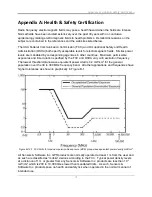
Page 83: ...xposures and time duration specified by the FCC and OSHA vary with excitation frequency The lowest threshold plane wave equivalent power cited is 0 2 mW cm2 for the general population over the 30 to 300 MHz frequency band All other applications and frequencies have higher tolerances as shown in graphically in Figure B 1 Figure B 12 1 FCC limits for maximum permissible exposure MPE plane wave equiv...

Page 84: ...Appendix A Health Safety Certification 72 ...

Page 85: ...ference and this device must accept any interference received including interference that may cause undesired operation Part 15 User Information This equipment has been tested and found to comply with the limits for a Class A digital device where applicable and for an ultra wide bandwidth UWB device where applicable pursuant to Part 15 of the FCC Rules These limits are designed to provide reasonab...

Page 86: ...rated directly by one of the described parties For example a GPR may be operated by a private company investigating forensic evidence for a local police department FCC Permitted Mode of Usage The GPR antenna must be kept on the surface to be in compliance with FCC regulations Use of the antenna is not permitted if it is lifted off the surface Use as a through the wall imaging device is prohibited ...

Page 87: ... contact will be provided Except for operation within these designated areas once the information requested on the UWB imaging system is submitted to the FCC no additional coordination with the FCC is required provided the reported areas of operation do not change If the area of operation changes updated information shall be submitted to the FCC following the procedure in paragraph b of this secti...

Page 88: ...CONTACT NAME AND PHONE NUMBER AREA OF OPERATION COUNTIES STATES OR LARGER AREAS FCC ID QJQ NG250 EQUIPMENT NOMENCLATURE NG250 Send the information to Frequency Coordination Branch OET Federal Communications Commission 445 12th Street SW Washington D C 20554 ATTN UWB Coordination Fax 202 418 1944 INFORMATION PROVIDED IS DEEMED CONFIDENTIAL ...

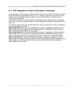
Page 89: ...ormation they should acquire copies of the following documents available from ETSI ETSI EN 302 066 1 V1 2 1 February 2008 Electromagnetic compatibility and Radio spectrum Matters ERM Ground and Wall Probing Radar applications GPR WPR imaging systems Part 1 Technical characteristics and test methods ETSI EN 302 066 2 V1 2 1 February 2008 Electromagnetic compatibility and Radio spectrum Matters ERM ...

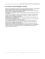
Page 90: ...truction companies and emergency rescue or firefighting organizations Should the ground penetrating radar be used in a wall penetrating mode then the following restriction should be noted by the user This In wall Radar Imaging Device shall be operated where the device is directed at the wall and in contact with or within 20 cm of the wall surface This In wall Radar Imaging Device shall be operated...

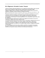
Page 91: ...es organisations de lutte contre les incendies Si le géoradar est utilisé dans un mode de pénétration au mur la restriction suivante est à noter par l utilisateur Ce dispositif d imagerie radar doit être utilisé lorsque l appareil est orienté vers le mur et en contact avec ou dans les 20 cm de la surface du mur Ce dispositif d imagerie radar doit être utilisé que par les organisations d applicatio...

Page 92: ...Appendix B GPR Emissions Interference and Regulations 80 ...

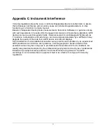
Page 93: ...lectromagnetic fields such as TV stations radio stations and cell phones can cause signals detectable by a GPR which may degrade the quality of the data that a GPR device records and displays Such interference is unavoidable but sensible survey practice and operation by an experienced GPR practitioner can minimize such problems In some geographic areas emissions from external sources may be so lar...

Page 94: ...Appendix C Instrument Interference 82 ...

Page 95: ...ecommend keeping the GPR transmitters at least 5 feet 2m from blasting cap leads as a precaution Some customers do experimental trials with their particular blasting devices to confirm with safety We strongly recommend that GPR users routinely working with explosive devices develop a systematic safety methodology in their work areas The UXO issue is more complex and standards on fuses do not exist...

Page 96: ...Appendix D Safety around Explosive Devices 84 ...

Page 97: ...ergy and if not installed and used in accordance with the instruction manual may cause harmful interference to radio communications Operation of this equipment in a residential area is likely to cause harmful interference in which case the user will be required to correct the interference at his her own expense Industry Canada Notice This device complies with Industry Canada s license exempt RSSs ...

Reviews: