Conquest 100
Tools & Setup
55
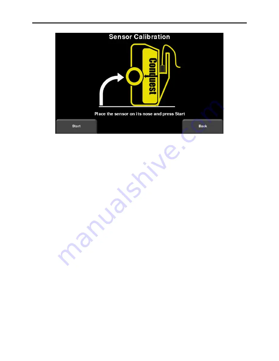
Figure 5-23: Running the GPR Sensor Test
Simply turn the Sensor Head such that it rests on the front (as shown in the image above) and
follow the instructions. There should be no objects near the bottom of the Sensor Head, as this
will affect the calibration results.
5.2.8 PCD Sensor
Ensures proper operation of the Power Cable Detector. The user will need the battery charger
to be plugged in and connected to the display unit for this test. Lower the sensor head down on
the battery charger and change the orientation of the sensor head with respect to the battery
charger (Figure 5-24). A successful test will show the Field Strength varying with the movement
of the sensor head, confirming proper operation. Press
Stop
then
Exit
when this has occurred.
Summary of Contents for CONQUEST 100
Page 1: ... Copyright 2015 Sensors Software Inc 2015 00049 05 ...
Page 2: ......
Page 4: ......
Page 10: ......
Page 16: ...Conquest 100 Overview 6 ...
Page 46: ...Conquest 100 Main Screen 36 ...
Page 84: ...Conquest 100 Line Scan 74 ...
Page 104: ...Conquest 100 SliceView 94 ...
Page 114: ...Conquest 100 Transferring Data to a PC 104 ...
Page 116: ...Conquest 100 Transferring Data to a PC 106 ...
Page 120: ...Conquest 100 Troubleshooting 110 ...
Page 124: ...Conquest 100 Care and Maintenance 114 ...
Page 128: ...Conquest 100 Technical Specifications 118 ...
Page 130: ...Conquest 100 Appendix A Health Safety Certification A2 ...
Page 140: ...Conquest 100 Appendix C Instrument Interference C2 ...
Page 142: ...Conquest 100 Appendix D Safety Around Explosive Devices D1 ...


