background image


QUICK START INSTRUCTIONS 

P

LEASE REFER TO THE REST OF THE INSTRUCTION MANUAL FOR MORE DETAILED INFORMATION

1.  Find a suitable location that is clean, dry, and in a gas-free area.  

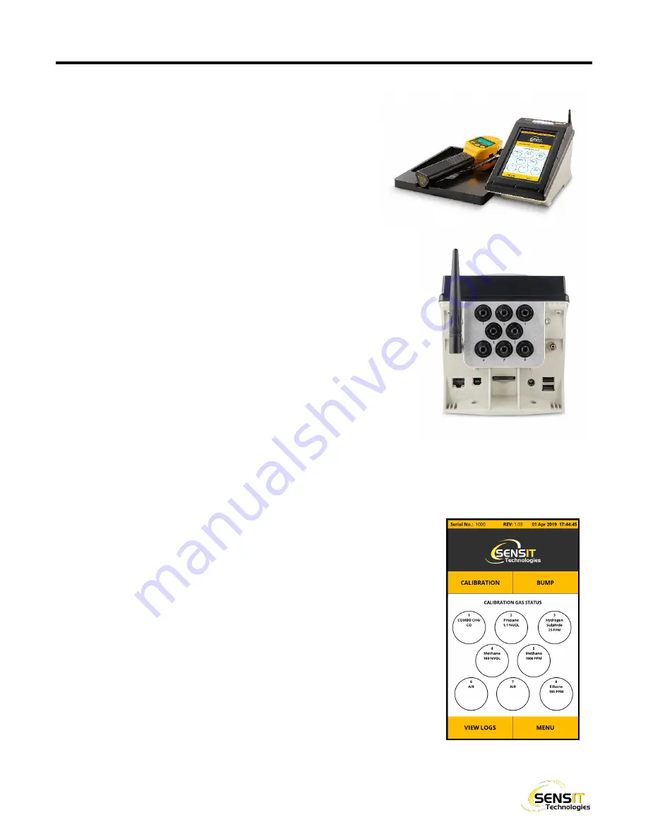
Install the SMART-CAL 360 base on the bottom of the station 

with the provided screws, as pictured.  Place the assembly onto 

a flat surface. 

2.  If  SCAL-360

–D  (desktop)  or  –N  (network)  software  is  to  be 

used, attach the appropriate USB or Ethernet cable(s).  Refer 

to instruction manual if utilizing Wi-Fi. 

3.  Attach  the  appropriate  blade  adapter  to  the  power  supply  and  plug  it 

into the power source and the back of the station.  The station will power 

on automatically, indicated by a blue status LED on the top of the unit. 

4.  Allow the station to complete the start-up process and reach the main 

display.  Press the CONTINUE button on the System Check screen to 

acknowledge and move on to the Home Screen. 

5.  Prepare the calibration gas: 

a.  Attach the regulators to the gas bottles. 

b.  Attach the included hoses in the hose kit to the regulators, the unit 

hose to the metal fitting on the back of the station, and the fresh air 
hose(s) to the appropriate “Air” port connection(s) shown as shown 
on-screen. 

c.  Attach the fittings on the hoses to the appropriate gas port connections on the back of the station as shown 

on-screen.  If the configuration shown does not match your needs, it can be re-configured in the Supervisor 

Menu (refer to the instruction manual and contact SENSIT Technologies for the password). 

d.  If using positive pressure regulators with ON/OFF knobs, turn them on. 

10.  Power on a compatible SENSIT instrument to be calibrated or bump tested.  

After  the  instrument  completes  the  warmup  process,  put  it  into  SMART-
CAL mode by pressing and holding the “A” button (left) for 1-2 seconds.  If 
performing a calibration, allow an additional 5-10 minutes of warmup time. 

11.  Place the instrument in the cradle and attach the instrument hose.  Press 

the CALIBRATION or BUMP button on the Home Screen of the station. 

12.  Allow the calibration or bump test process to complete.  The result will be 

given on-screen at the end, and the LED on the top of the unit will reflect 

the result: 

●  WHITE – ready 
●  BLUE – busy / in progress 
●  YELLOW – check gas supply 
●  GREEN – calibration passed 
●  RED – calibration failed 

Summary of Contents for SMART-CAL 360

Page 1: ...ON STATION INSTRUCTION MANUAL READ AND UNDERSTAND INSTRUCTIONS BEFORE USE 851 Transport Drive Valparaiso IN 46383 8432 Email info gasleaksensors com Web www gasleaksensors com Phone 888 473 6748 219 465 2700 Fax 219 465 2701 ...

Page 2: ...e to the metal fitting on the back of the station and the fresh air hose s to the appropriate Air port connection s shown as shown on screen c Attach the fittings on the hoses to the appropriate gas port connections on the back of the station as shown on screen If the configuration shown does not match your needs it can be re configured in the Supervisor Menu refer to the instruction manual and co...

Page 3: ...e by a factory certified technician WARNING Follow the manual instructions and testing methods WARNING Only use in areas that are known to be free of combustible gas hazards WARNING Only for use in areas that are clean and dry WARNING Turn all regulators and or gas valves off when the SMART CAL 360 is not in use WARNING If your calibration setup has line gas plumbed directly into the station inste...

Page 4: ...fications 8 Installation and Setup 9 Valve Configuration 10 Operation and Use 11 Performing a Calibration 11 Performing a Bump Test 12 Viewing Logs 13 SD Card Features 13 Database Backup and Restore 14 Software Updates 14 Supervisor Menu 15 Maintenance and Care 16 Filter Replacement 16 Troubleshooting 17 Flow Block Check Issues 17 Communication Issues 17 Check Gas Supply Errors 18 Notes 19 EU Wast...

Page 5: ... 00064 Instruction Manual 750 00086 Calibrator protective dust cover 360 00636 SD Card 360 00243 SCAL 360 Data Management Software 500 SC360 01 DESKTOP VERSION USB Cable 360 00637 NETWORK VERSION Ethernet Cable 360 00027 Wi Fi Antenna 360 00481 ACCESSORIES AND REPLACEMENT PARTS SCAL 360 License Renewal 500 SC360 02 Gas Input Fittings with filter 360 00520 ...

Page 6: ...e data on screen and perform bump tests The calibrator can be used as a stand alone device or with SCAL 360 Data Management Software See software setup section for specific requirements and instructions The calibrator automatically records all calibration and bump test attempts whether pass or fail to ensure 100 compliance The on board memory can store up to 6 000 calibration records and 12 000 bu...

Page 7: ...f stations over a company s network regardless of their physical locations SCAL N 360 operates within the network and does not require an internet connection All stations share one central SQL server database allowing instrument users to calibrate bump test their instruments at any location The administrator using SCAL N 360 Admin adds stations and locations downloads data and can assign superviso...

Page 8: ... Storage Temperature 32 F to 122 F 0 C to 50 C Maximum Input Pressure 30 PSI 2 Bar Supported Instruments as of 27 Mar 20 Legacy IR Communication SENSIT HXG 3 HXG 3P SENSIT Gold Gold 100 Gold CGI Trak IT III CGI SENSIT CO HCN SENSIT Gold G2 TRAK IT IIIa SENSIT PMD IRED Data Storage Capacity 6 000 Calibration Records 12 000 Bump Test Records 120 Gas Cylinder Logs If using an on demand style regulato...

Page 9: ...rocess on the station is complete the main display should be shown On this display will be the default valve configuration which covers most standard calibration kits If you need to change this configuration based on the calibration gas you will be using for your instruments first follow the steps listed in the next section for valve configuration then proceed with these instructions 5 Attach the ...

Page 10: ...ion gas that isn t listed above or if you need to change the existing configuration configure the valves by following the instructions below 1 From the main display select the menu button on the bottom right 2 Enter the supervisor password contact SENSIT if you need the password Supervisor Menu should appear at the top of the screen 3 Locate and select Valve Configuration from the list 4 For each ...

Page 11: ...cessary check the instruction manual for your specific instrument 3 Place the instrument into the proper cutout position of the cradle and attach the instrument hose to the inlet of the instrument For Trak It instruments a pig tail assembly is required 4 On the SMART CAL 360 press the CALIBRATION button Searching will be displayed while the station and instrument establish communication After it h...

Page 12: ...let of the instrument For Trak It instruments a pig tail assembly is required 4 On the SMART CAL 360 press the BUMP button Searching will be displayed while the station and instrument establish communication After it has been established and the model type and serial number of the instrument are displayed no other input is required Calibration will proceed and give a result after completion Bump t...

Page 13: ...ill be displayed which organizes records by first by instrument type After the appropriate instrument type is selected all records for that type are displayed organized by date and time Each record will also show the instrument serial number whether the record is for a calibration or bump test and what the result was When a record is selected a breakdown is shown for the result of each test perfor...

Page 14: ...eature enabled which means that once per day the station will automatically create and save a backup This will be done up to 10 times before the oldest backup is erased Backups can also be created manually from the Backup Restore Database menu in the Supervisor menu Contact SENSIT Technologies if you need assistance with this feature SOFTWARE UPDATES SMART CAL 360 software can be updated by the us...

Page 15: ...IGURATION Resets the valve configuration to the default setup CYLINDER TRACKING Enable or disable cylinder tracking feature This allows the user to enter details about each gas cylinder attached to the station such as expiration date and lot numbers This information can then be retrieved by SCAL 360 Data Management software to send alerts related to gas usage ERASE CAL BUMP LOGS Password protected...

Page 16: ... the back of the station Over time is it possible these filters may become clogged with debris or oils from inside the gas cylinders which would result in Check Gas Supply errors If this happens or if the filter looks damaged or frayed the filter will need to be replaced To replace a filter 1 Disconnect the tubing from the fitting and remove the old filter using a 9 16 15mm wrench or socket The pl...

Page 17: ...ooks good place a finger over the inlet of the instrument Within 5 seconds a flow blocked message should appear on screen If that message does not appear or if it takes a significant amount of time the sampling system of the instrument isn t sealed properly If the instrument shows the flow block message properly check the instrument hose by attaching it to the instrument as you normally would and ...

Page 18: ...You should hear and or feel a release of pressure 3 Inspect the filter fitting on the valve that is giving the error and the fitting on the hose that attaches to it Make sure the connection isn t loose and neither fitting has a visible crack If no obvious issues are found temporarily replace the filter either with a new one or from a valve position that isn t being used a Disconnect the tubing fro...

Page 19: ...___________________________________________________________ __________________________________________________________________________________________ __________________________________________________________________________________________ __________________________________________________________________________________________ ___________________________________________________________________...

Page 20: ...oducts with the WEEE Symbol figure above to alert our customers that products bearing this label should not be disposed of in a landfill or with municipal or household waste in the EU WARRANTY Your SMART CAL 360 is warranted to be free from defects in materials and workmanship for a period of two years after purchase If within the warranty period your instrument should become inoperative from such...

Reviews: