B-8
CamCor CT and PRO Series Hardware Manual
Appendix B
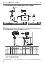
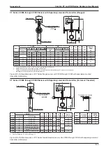
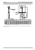
CT Series CC100 and CC150 Sensor (High-temperature) with Separately-mounted Transmitter (Flanged)
300
1387
1015
660
810
98
L
107
Conduit connection
3/4-14 FNPT
(M25)
Terminal box
15
Flow direction
Flange
Ground screw
Boss
1/4-18
FNPT
Model
Flange
L
(mm)
Approx.
Weight (kg)
Nominal size Flange rating
CC100
4"
ASME 150
1018
237
ASME 300
1036
245
ASME 600
1082
255
DN100
PN 10, 16
968
231
PN 25, 40
994
241
CC150
6"
ASME 150
1318
248
ASME 300
1338
265
ASME 600
1388
292
DN150
PN 10, 16
1250
246
PN 25, 40
1290
265
1. Conduit connections are 3/4-14 FNPT for CSA units and M25 for
ATEX units.
2. For specifications of other flange ratings, see the approval drawing
(or delivery specification).
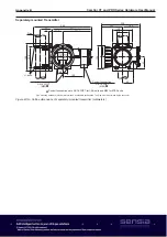
Figure B.12—Outline dimensions of CT Series flanged sensor units CC100 and CC150 with separately-mounted transmitter
(millimeters)
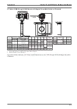
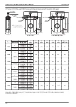
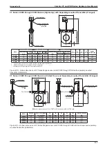
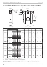
CT Series CC025 through CC080 Sensor (Low-temp.) with Separately-mounted Transmitter (Flanged)
Conduit connection
3/4-14 FNPT
(M25)
A
W
h1
10
H
Ground screw
107
98
L
Flow direction
Flange
Model
ASME
DIN
H
(mm)
h1
(mm)
A
(mm)
W
(mm)
Approx.
Weight (kg)
Nominal
size (mm)
150
300
600
900
Nominal
size (DN)
PN 10, 16 PN 25, 40
L (mm)
L
CC025
25
411
424
437
460
25
376
380
660
329
83
262
10.9
CC040
40
547
560
575
603
40
507
513
790
452
121
385
20.3
CC050
50
550
563
582
641
50
513
519
790
452
121
385
21
CC080
80
699
717
727
777
80
659
675
960
602
174
510
54
1. Conduit connections are 3/4-14 FNPT for CSA units and M25 for ATEX units.
2. ASME 900 flanges are only available in Alloy C22 material.
• This table only applies to meter material SUS316L. For information about material Alloy C22, please consult Cameron.
• DIN flanges are only available for meter material SUS316L.
Figure B.13—Outline dimensions of CT Series flanged sensor units CC025 through CC080 with separately-mounted
transmitter (millimeters)
Summary of Contents for CamCor CC001
Page 14: ...14 CamCor CT and PRO Series Hardware Manual Section 3 This page is left blank intentionally ...
Page 24: ...24 CamCor CT and PRO Series Hardware Manual Section 3 This page is left blank intentionally ...
Page 54: ...54 CamCor CT and PRO Series Hardware Manual Section 5 This page is left blank intentionally ...
Page 62: ...62 CamCor CT and PRO Series Hardware Manual Section 7 This page is left blank intentionally ...

