CamCor CT and PRO Series Hardware User Manual
B-1
Appendix B
Appendix B—Product Dimensions (Metric Units)
tion 4—Product Dimensions (U.S. Customary Units)
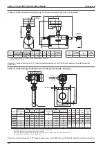
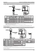
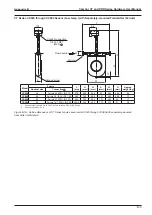
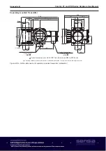
CT Series CC00A and CC001 Sensor with Separately-mounted Transmitter (Threaded)
9.06
3.86
8.27
9.33
7.05
1.18
5.63
4.21
0.63
6.89
2.48
1.46
1/4-18 FNPT
process connection
Ground screw
Terminal box
(4) 9 fitting hole
(fits M8 bolt)
Conduit
connection
3/4-14 FNPT
(M25)
2.05
Flow direction
Conduit connections are
3/4-14 FNPT for CSA units
and M25 for ATEX units.
Approx. weight: 9 kg
Figure B.1—Outline dimensions of CT Series sensor units CC00A and CC001 (millimeters)
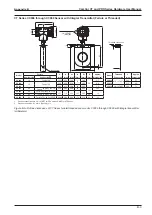
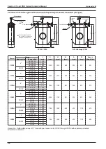
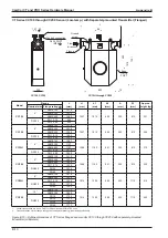
CT Series CC003 Sensor with Separately-mounted Transmitter (Flanged)
L
A
W
98
H
h1
Ground screw
Conduit connection
3/4-14 FNPT
(M25)
98
107
109
10
Model
ASME
DIN
H
(mm)
h1
(mm)
A
(mm)
W
(mm)
Approx.
Weight
(kg)
Nominal size
(mm)
150
300
600
900
Nominal size
(DN)
PN 10, 16 PN 25, 40
L (mm)
L (mm)
CC003
10
301
310
322
338
15
275
281
230
67
89.1 192
5.0
1. Conduit connections are 3/4-14 FNPT for CSA units and M25 for ATEX units.
2. ASME 900 flanges are only available in Alloy C22 material.
• This table only applies to meter material SUS316L. For information about material Alloy C22, please consult Cameron.
• DIN flanges are only available for meter material SUS316L.
Figure B.2—Outline dimensions of CT Series flanged sensor unit CC003 with separately-mounted transmitter (millimeters)
Summary of Contents for CamCor CC001
Page 14: ...14 CamCor CT and PRO Series Hardware Manual Section 3 This page is left blank intentionally ...
Page 24: ...24 CamCor CT and PRO Series Hardware Manual Section 3 This page is left blank intentionally ...
Page 54: ...54 CamCor CT and PRO Series Hardware Manual Section 5 This page is left blank intentionally ...
Page 62: ...62 CamCor CT and PRO Series Hardware Manual Section 7 This page is left blank intentionally ...

