
General
This operation and installation manual provides
general guidelines and suggestions to assist
you in using the SensComp, Inc. MINI-S ultra-
sonic sensor module in many measurement
applications. For additional information, please
contact a SensComp Applications Engineer at
(734) 953-4783 between 9 AM and 5 PM EST.
General Installation Procedures
1. Always mount the MINI-S in a suitable dry
location. The MINI-S is designed to be used
in an indoor or protected environment only.
The MINI-SE is suitable for harsher environ-
ments and higher humidity conditions.
Excessive moisture on the circuit board (and
the MINI-S transducer) will result in damage
and improper operation, and will void all
warranties.
2. Mount the MINI-S as far off the ground as
practical.
3. Mount the MINI-S in a location where
environmental interference sources are
minimized (examples are EMI sources, air
nozzles, excessive air turbulence, etc.).
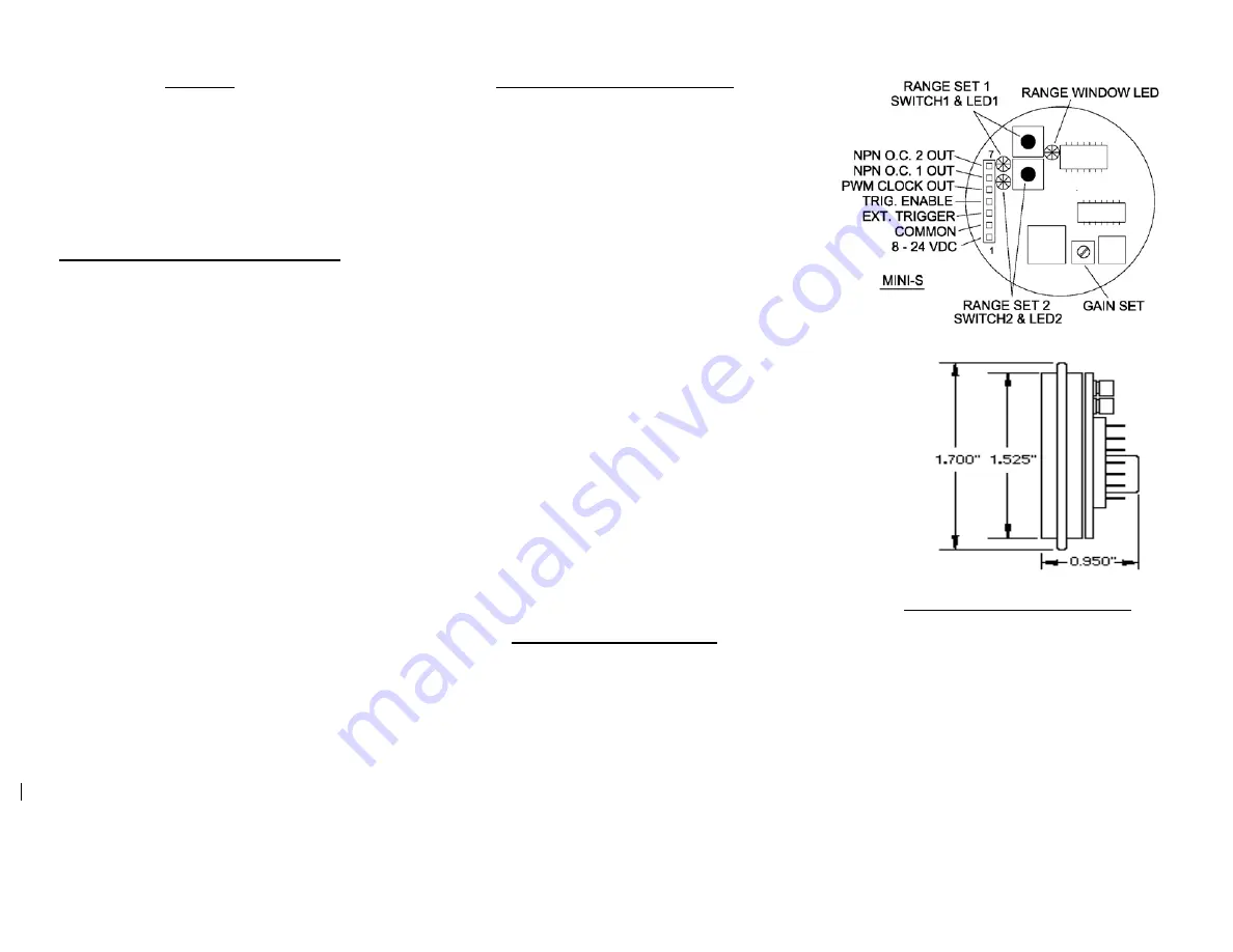
4. Mount the MINI-S in a 1.575 inch diameter
hole, using RTV silicone or edge clips to
secure the sensor in place. You can also
use our Series 600 Housing unit, PID#
619395, to house the MINI-S.
5. As supplied, the MINI-S has been calibrated
and will function without further calibration.
6. The two (2) NPN open collector digital out-
puts need to be “pulled up” (through a resis-
tance and/or impedance) to an external
positive power source of less than 40 VDC.
(typically 4700 ohms when connected to an
ex5 VDC power source for testing or
for interfacing to TTL Logic level circuits).
The maximum output current is 600 mA. The
Range Set LEDs do not require pull-up
resistors, and can be used for setup
calibration before connecting the MINI-S to
external equipment.
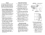
System Wiring Information
Pin 1 – Power Supply – A +8 to +24 VDC
regulated power source supplying 30 mA of
current (2.0 Amperes during the 0.5 ms
transmit pulse).
Pin 2 – Power Supply Common (Ground) –
Common Return for DC power supply,
switched outputs, and clock signals.
Pin 3 – External Trigger – Accepts TTL com-
patible logic level clock signals. A low to
high (zero to +5 VDC) transition triggers
the MINI-S
Pin 4 – Trigger Enable – Allows the MINI-S to
accept an external trigger signal. Enabled
by connecting this pin (pin 4) to common
(pin 2).
Pin 5 – Clock Output – Delivers a TTL com-
patible Pulse Width Modulated (PWM) clock
signal. This signal goes high at the start of
a cycle, and returns to a low state when the
returning echo is received.
Pin 6 – NPN Output 1 – This NPN open collector
output turns on and off when a target is
detected (on) or missing (off) as set by the
Range Set 1 push button.
Pin 7 – NPN Output 2 – This NPN open collector
output turns on and off when a target is
detected (on) or missing (off) as set by the
Range Set 2 push button.
Calibration Procedures
1. Apply DC power ( +8 to +24 VDC) to the
MINI-S (connector header pins 1 and 2)
2. Allow five to ten minutes warm-up time for
the MINI-S to reach operating tempera-
ture before calibrating the unit.
3. If desired for testing, connect the two
NPN Open Collector Outputs to an
external positive power supply through
appropriate impedances. Since they are
open collector, they will always read zero
volts until connected to a pull-up load
(See General Installation Procedures –
Step 6).
4. NPN Output 1 Adjustment (pin 6)
•
Place the target at the desired
detection distance from the face of
the MINI-S.
•
Depress and hold the “Range Set 1”
push button switch. Wait for the
“Range Window” LED to flash three
times, followed by a “chirp” sound
from the sensor before releasing.
•
The NPN output 1 should now be set:
o
LED 1 ON – NPN output is a
Logic Low (0 VDC) when target
is detected.
o
LED 1 OFF – NPN output is a
Logic High (+ power source)
when target is not detected.