Troubleshooting VCR Luminance Circuits With
The VC93 All Format VCR Analyzer
A VCR contains five major sections: lumi-
nance, chroma, audio, servo, and system
control. The luminance section of a VCR
receives the FM signal from the tape and
processes it into a form that can be used by
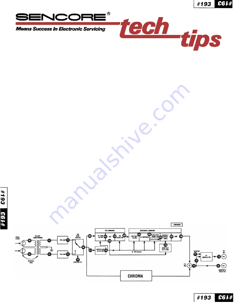
a television or monitor. The blockdiagram in
Figure 1 shows the luminance section of a
VCR. Defects in any of these luminance stages
produce the same symptom - a snowy or
muted playback picture. This often makes
isolating the symptom to a specific circuit
difficult.ThisTechTipexplains how to trouble-
shoot the luminance section of a VCR using
the signals supplied by the VC93.
Before explaining how to use the VC93, let’s
briefly review how the luminance stages func-
tion and what signals are found at each block
during playback.
How The Luminance Signal Is
Processed
The FM luminance signal begins at the video
heads. After the spinning heads pick up the
signal, it is coupled through the rotary trans-
former windings and fed to the head pream-
plifiers. The outputfrom the head preamps is
selected by the A/B head switcher. Only the
signal from the head which is in contact with
the tape is fed to the remaining circuits. This
keeps unwanted noise from the head not in
contact with the tape from getting into the
picture.
After the A/B headswitcher, the FM lumi-
nance signal is separated from the down-
converted chroma signal. The color and lu-
minance signals are processed separately
until they are combined in the Y/C mixer. The
signal at the Y/C mixer output is composite
video which is fed to the VIDEO OUT jack and
RF modulator. The VC93 provides the special
luminance signals needed to troubleshoot
the circuits from the video heads to the RF
modulator.
The make up of the FM luminance signal is
different for each VCR format (VHS, Beta, U-
Matic, & 8MM). The VC93 generates the
necessary luminance signals needed for each
VCR format. For specific information on the
VCR formats refer to Tech Tip #189, “Com-
parison Of VCR Formats.”
Troubleshooting The Luminance
Signal Path
The VCR luminance signal path can be di-
vided into three major sections for trouble-
shooting:
1. The video head channel
2. The FM luminance stages
3. The video stages
Since the video heads pick up the tape signal,
the head channel is a good place to begin
signal injection.
Injecting the VC93 “Lum” PLAYBACK SIG-
NAL at the input of both preamps simulta-
neously will prove whether or not the FM
luminance circuits and the video circuits that
follow are able to process a good signal. Use
the “Playback Head Sub” position of the
PLAYBACK RANGE switch when injecting
into the head channel. If the circuits properly
process the VC93 signal (as indicated by the
“Color Bars” pattern on the playback moni-
tor), you have narrowed the problem to the
video heads or to the rotary transformer. For
additional information on testing the head
circuits refer to Tech Tip #194, “Trouble-
shooting ‘Bad Head’ Symptoms With The
VC93 All Format VCR Analyzer.”
If your injection into the head channel fails to
return a picture on the playback monitor, a
Fig. 1: The luminance signal path in a VCR.


