background image

MRD 7000 

– User Manual 

Page 98 (126)


Once the SSA period has expired, customers are free to keep using the software version 
they already have or other versions from before the expiration date but applying newer 
versions will require an extended SSA. 


3.3.20 

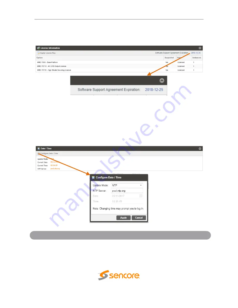
Date/Time 

The MRD can be set to synchronize with an NTP server, or a manual data and time can 
be defined by the user. Click the Configure Date / Time button to configure the date and 
time. These values are used to timestamp entries in the Alarm and Event logs under the 
Reporting tab.  


Setting


Range


Description


Update Mode 

NTP 

Manual 

Setting to 

NTP

 uses the local network

’s NTP 

server to synchronize date and time. 

Manual


allows the user to define a date and time. 

Summary of Contents for MRD 7000

Page 1: ...December 2022 8175Q www sencore com 1 605 978 4600 Revision 1 15 MRD 7000 Receiver Decoder Software User Manual ...

Page 2: ...hould be made directly to those companies This document may also have links to third party web pages that are beyond the control of Sencore The presence of such links does not imply that Sencore endorses or recommends the content on those pages Sencore acknowledges the use of third party open source software and licenses in some Sencore products This freely available source code can be obtained by...

Page 3: ...3 Feature Release ACD 05 21 2019 1 4 Feature Release BRW 10 03 2019 1 5 Feature Release JDF 05 18 2020 1 6 Feature Release JDN 05 27 2020 1 7 Updated Genlock Settings JDN 05 29 2020 1 8 Updated Specifications Appendix ACD 07 07 2020 1 9 Feature Release JDN 01 06 2021 1 10 Feature Release JDN 05 20 2021 1 11 Feature Release JDN 03 14 2022 1 12 Feature Release JDN 06 21 2022 1 13 Feature Release JDN...

Page 4: ...s have fallen into the apparatus the apparatus has been exposed to rain or moisture does not operate normally or has been dropped Do not expose this apparatus to dripping or splashing and ensure that no objects filled with liquids such as vases are placed on the apparatus To completely disconnect this apparatus from the AC Mains disconnect the power supply cord plug from the AC receptacle The main...

Page 5: ... application or operation email ProCare Sencore com WARNING To reduce the risk of fire or electrical shock never allow your equipment to be exposed to water rain or high moisture environments If exposed to a liquid remove power safely at the breaker and send your equipment to be serviced by a qualified technician To reduce the risk of shock the power supply must be connected to a mains socket outl...

Page 6: ...of the items that are included 1 MRD 7000 Chassis 2 MRD 7000 Software 3 AC Power Cable 4 Breakout or Adapter Cables Depending on Option Modules 5 Quick Start Guide If any of these items were omitted from the packaging please email ProCare Sencore com to obtain a replacement ...

Page 7: ...7 Configuring Satellite Input 41 3 2 1 8 Configuring RTMP Input 43 3 2 1 9 Configuring HLS Input 45 3 2 2 Configuring Conditional Access 47 3 2 2 1 BISS1 Descrambling 47 3 2 2 2 BISS2 Descrambling 48 3 2 3 Configuring Transport Stream Processing 49 3 2 4 Configuring Decoding and Service Selection 50 3 2 4 1 Advanced Configuration 51 3 2 5 Configuring Baseband Processing 52 3 2 5 1 Configuring Vide...

Page 8: ... Decoder Output Modes 90 3 3 18 1 Configuring SDI Single Port UHD Decoder Outputs 90 3 3 18 2 Configuring SDI Multichannel Decoder Outputs 92 3 3 18 3 Configuring SDI Quad Link UHD Decode Outputs 93 3 3 18 4 Configuring 2110 Single Link UHD Decode Outputs 95 3 3 18 5 Configuring 2110 Multichannel Decoder Outputs 96 3 3 19 Licensing 97 3 3 19 1 Software Support Agreements 97 3 3 20 Date Time 98 3 3...

Page 9: ...MRD 7000 User Manual Page 9 126 Section 1 Overview Introduction This section includes the following topics 1 1 PRODUCT INTRODUCTION 10 1 2 FRONT PANEL OVERVIEW 11 1 3 REAR PANEL OVERVIEW 11 ...

Page 10: ...D SDI SD SDI HDMI 2 0a and SMPTE 2110 support Every MRD 7000 ships with the software suite pre loaded on appropriate hardware There are optional output configurations that will change the physical connectors available on the back of the chassis Input Capabilities 4x ASI 4x Satellite 2x RJ45 GigE Ethernet Ports o UDP RTP MPEG IP Transport Streams o Unicast o Multicast o SMPTE 2022 7 hitless switchi...

Page 11: ...ator lights email ProCare Sencore com 1 3 Rear Panel Overview The MRD 7000 server has multiple options for the backplane configuration Both options include dual network ports on the motherboard Either port can be used to access the web interface or receive DATA IP For QUAD 3G 4x BNC cables to carry one video format such as 4K 1 Breakout connector used for Genlock Input requires breakout cable 2 To...

Page 12: ...P 6 Local monitor output uses VGA D SUB connector 7 Redundant power supplies 120 240 AC Switching PS VGA and keyboard are only used for setting the network configuration operation of the device is performed through the web interface For SMPTE 2110 Playback 1 Data Path A One of two SFP ports for SMPTE 2110 uncompressed video over IP 2 Data Path B One of two SFP ports for SMPTE 2110 uncompressed vid...

Page 13: ...configuration operation of the device is performed through the web interface For 12G SDI and Quad 3G SDI Playback and Genlock 1 SDI port 1 for 12G SDI w embedded audio ASI or SD HD 3G SDI w embedded audio SDI ports labeled 1 through 4 2 Bi level and tri level genlock input port 3 Eth0 One of two available RJ45 Ethernet ports for management of MPEG IP 4 Eth1 One of two available RJ45 Ethernet ports...

Page 14: ... power supplies 120 240 AC Switching PS VGA and keyboard are only used for setting the network configuration operation of the device is performed through the web interface For Added IP Input Ports MRD 70200 IP Card 1 Eth0 One of four available RJ45 Ethernet ports for management or MPEG IP 2 Eth1 One of four available RJ45 Ethernet ports for management or MPEG IP 3 Eth2 One of four available RJ45 E...

Page 15: ... Manual Page 15 126 Section 2 Installation Introduction This section includes the following topics 2 1 RACK INSTALLATION 16 2 2 AC DUAL REDUNDANT POWER CONNECTIONS 16 2 3 MAINTENANCE 16 2 4 NETWORK SETUP VIA KVM 17 ...

Page 16: ... 2 2 AC Dual Redundant Power Connections The Dual Redundant option allows the MRD to be powered by two separate supplies either operating 120V or 240V systems The power supply will automatically detect the system it is connected to To hook up the power use the following steps 1 Locate the AC power cords that are included 2 Plug the female end of the power cords end with no prongs into the back of ...

Page 17: ...text based menu to configure IP addressing Subnet Mask Gateway and DNS settings Sencore recommends configuring the Eth0 port Leftmost NIC when facing the rear of the unit be set to a static IP for web interface access Ensure the user machine is also on the same network For additional information on initial network configuration menu see the Sencore MRD 7000 Quick Guide documentation ...

Page 18: ...age 18 126 Section 3 Web Interface Operation Introduction This section includes the following topics 3 1 MRD 7000 WEB INTERFACE OVERVIEW 19 3 2 DECODER PANEL 21 3 3 ADMIN PANEL 73 3 4 REPORTING PANEL 101 3 5 ABOUT PANEL 104 ...

Page 19: ...rer 7 above Firefox 3 5 above Google Chrome Microsoft Edge The user will need to login to the web interface Press the login button to login to the web interface Default Credentials Username admin Password mpeg101 3 1 2 Hiding Unused Inputs The MRD 7000 web interface allows the user to hide inactive inputs using the button or show all available inputs by click the button Only the selected input wil...

Page 20: ...ation All text in status menus shown in ORANGE are user configurable settings Text shown in BLUE is not user configurable and is strictly a status or value To minimize the status windows again click the icon Status in the MRD 7000 web interface is shown with LED status indicators Green LED Status is good No errors are present and function is operating normally Red LED Status indicates function is ...

Page 21: ...the MRD 7000 can detect the failed state and switching to a secondary backup input to provide a continuous output Which input is primary and backup how the inputs switchover and restore and switchover timing is all user configurable Input options include File Input MPEG IP Stream 1 MPEG IP Stream 2 RTMP Input 1 RTMP Input 2 ASI Port 1 ASI Port 2 ASI Port 3 ASI Port 4 SRT Input 1 SRT Input 2 Seamle...

Page 22: ...rowsing to the MRD s IP address using FTP or Windows file sharing Active Input and Failover Configuration Menu Setting Range Description Primary Input File Input MPEG IP Stream 1 MPEG IP Stream 2 ASI Port 1 4 RTMP Input 1 RTMP Input 2 SRT Input 1 SRT Input 2 Seamless RTP HLS Input 1 HLS Input 2 Zixi Input 1 Zixi Input 2 Satellite Port 1 4 None Used for both normal operation and input failover sett...

Page 23: ...y to the backup input if the primary stream loses synchronization for the duration of the Switchover Interval Decode Failure the unit will switch to the backup input when it encounters decoding errors on the primary input Restore On Manual Only Primary Input TS Restored Backup Input TS Sync Loss Decode Failure Manual Only the unit will not restore to the primary input automatically The user must m...

Page 24: ...the gear allows the user to configure the desired input port and network destination parameters Setting Range Description Receive Enabled Disabled This setting allows the user to enable or disable these input stream settings Physical Connector Eth0 Eth1 The physical connector on the MPEG IP card that will be used to receive the input Mode Multicast Unicast Multicast setting allows the unit to rece...

Page 25: ...ks supporting IGMPv3 If this setting is set to Exclude any streams originating from the user defined IP addresses will be rejected If this setting is set to Include any streams originating from the user defined IP addresses will be received Once the MRD is locked on an MPEG IP signal the indicator light on the right will turn green and the received bitrate is displayed Sync status the number of tr...

Page 26: ...MRD 7000 User Manual Page 26 126 The MRD 7000 can also display the individual Program Service numbers by clicking on the Table Viewer hyperlink ...

Page 27: ... 2 1 2 Configuring File Input When File Input is selected as the active input clicking on the gear icon allows the user to choose source file After Input File has been chosen user has a possibility to Play Stop Set Start Stop End Points ...

Page 28: ...MRD 7000 User Manual Page 28 126 Once the File Input is played out the indicator light on the right will turn green and the progress bar will be activated ...

Page 29: ...MRD 7000 User Manual Page 29 126 The MRD 7000 can also display the individual Program Service numbers by clicking on the Table Viewer hyperlink ...

Page 30: ...g ASI Input When ASI Input is selected as the active input clicking on the gear icon allows the user to enable disable ASI ports Once the MRD is locked on ASI signal the indicator light on the right will turn green and the received bitrate is displayed ...

Page 31: ...MRD 7000 User Manual Page 31 126 The MRD 7000 can also display the individual Program Service numbers by clicking on the Table Viewer hyperlink ...

Page 32: ...user to enable or disable these input stream settings Physical Connector Eth0 Eth1 The physical connector on the MPEG IP card that will be used to receive the input Call Mode Caller Listener Rendezvous Defines the handshake mechanism to be used when establishing connection Remote Host xxx xxx xxx xxx or URL Defines the IP address or domain name of the stream on the remote device Remote Port 1 6553...

Page 33: ...ize in milliseconds Once the MRD is locked on an SRT signal the indicator light on the right will turn green and the received bitrate is displayed Connection state up time local port encryption mode decryption state Round Trip Time Buffer Size Latency and Link Bandwidth are shown under Status Statistics are displayed representing number of Reconnections number of Received Packets amount of Receive...

Page 34: ...MRD 7000 User Manual Page 34 126 The MRD 7000 can also display the individual Program Service numbers by clicking on the Table Viewer hyperlink ...

Page 35: ...le these input stream settings Path Sync Buffer Size ms 1 200 ms Used to increase or decrease the buffer time between path 1 2 Changing the size of this buffer will change how much time the MRD 7000 will buffer between the early arriving path and the late arriving path Path 1 2 Setting Range Description Physical Connector Eth0 Eth1 The physical connector on the MPEG IP card that will be used to re...

Page 36: ...sses will be received Once the MRD is locked on an RTP Seamless signals the indicator light on the right will turn green and the received bitrate is displayed Sync status number of active paths the number of transport stream packets inside the UDP payload and encapsulation type are shown under Status For both paths statistics are displayed representing Out of Order Packets Duplicate Packets Lost P...

Page 37: ...MRD 7000 User Manual Page 37 126 The MRD 7000 can also display the individual Program Service numbers by clicking on the Table Viewer hyperlink ...

Page 38: ...or on which to receive the Zixi traffic Remote Host xxx xxx xxx xxx or URL The IP address or domain name of the remote host broadcaster Alternate Remote Host xxx xxx xxx xxx or URL The alternate IP address or domain name of the remote host broadcaster Remote Port 1 65535 Defines the port of the stream on the remote device Stream ID Specified by Zixi broadcaster Zixi stream ID Password 1 128 charac...

Page 39: ...e FEC Once the MRD is locked on a Zixi signal the indicator light on the right will turn green and the received bitrate is displayed Connection state up time local port decryption state Round Trip Time Jitter are shown under Status Statistics are displayed representing number of Reconnections number of Received Packets amount of Received Bytes Dropped Packets Not Recovered Packets Not Recovered Pa...

Page 40: ...MRD 7000 User Manual Page 40 126 The MRD 7000 can also display the individual Program Service numbers by clicking on the Table Viewer hyperlink ...

Page 41: ...191 Satellite Input Module is installed When Satellite Input is selected as the active input clicking on the gear icon allows the user to enable disable Satellite ports Once the MRD is locked on a Satellite signal the indicator light on the right will turn green and the received bitrate is displayed ...

Page 42: ...MRD 7000 User Manual Page 42 126 The MRD 7000 can also display the individual Program Service numbers by clicking on the Table Viewer hyperlink ...

Page 43: ...on box Setting Range Description Receive Enabled Disabled Enable Disable the RTMP Input Physical Connector Eth0 Eth1 The physical Ethernet connector on which to receive the RTMP traffic Source URL xxx xxx xxx xxx or URL The IP address or domain name of the remote host broadcaster Once the MRD is locked on a RTMP signal the indicator light on the right will turn green and the received bitrate is di...

Page 44: ...MRD 7000 User Manual Page 44 126 The MRD 7000 can also display the individual Program Service numbers by clicking on the Table Viewer hyperlink ...

Page 45: ...l Connector Eth0 Eth1 The physical connector on which to receive the HLS traffic HLS Mode Pull Sets HLS to receive through a network location HLS Network Location XXX XXX XXX XXX or URL Defines address of the HLS stream to be received Decryption Mode Disabled AES128 Defines if a decryption of the received signal is needed AES 128 standard Decryption Key User Entry Provides the key to allow signal ...

Page 46: ...on the right will turn green and the received bitrate is displayed The Encryption Mode is shown under Status Configurations are displayed representing the Profile and Discovery Timeout The MRD 7000 can also display the individual Program Service numbers by clicking on the Table Viewer hyperlink ...

Page 47: ...on the gear icon allows the user to configure BISS1 Setting Range Description Operation Mode Enabled Disabled Enable Disable BISS descrambling Selected Key Key 1 12 Select a key to configure Alias 16 characters Set an Alias for the selected key Mode Mode 1 Mode E This setting sets the Mode of the BISS key that has scrambled the transport stream Mode 1 Session Word N A If Mode 1 is selected the use...

Page 48: ...the user to configure BISS2 Setting Range Description Operation Mode Enabled Disabled Enable Disable BISS descrambling Selected Key Key 1 12 Select a key to configure Alias 16 characters Set an Alias for the selected key Protocol BISS 1 BISS 2 Select which mode of BISS descrambling Mode Mode 1 Mode E Mode CA This sets the Mode of the BISS key that has scrambled the transport stream Mode 1 Session ...

Page 49: ...lic Key Download If Mode CA Buried is selected the user can download the Public Key from the MRD 7000 The file will be generated as a pub Mode CA Private Key Upload If Mode CA Injected is selected the user will need to upload the Private Key The file name length must be less than 20 characters The supported file types are txt or priv 3 2 3 Configuring Transport Stream Processing Setting Heartbeat ...

Page 50: ...ice Lock The MRD will decode the first service found Locks the decoder to defined service number Service Number Click the drop down to select a service number This list will be populated by all services in the incoming transport stream This will also include the Service Name and the Service Type When the MRD 7000 begins decoding a service the Additional Data status will report HDR metadata SMPTE 2...

Page 51: ...ended unless minimal latency is crucial to the application Clicking the Restore Defaults button will reset all values to the default values Setting Range Description MPEG2 1 50 The parallel frames processed when decoding MPEG2 video H264 1 50 The parallel frames processed when decoding H264 video HEVC 1 50 The parallel frames processed when decoding HEVC video JPEG2000 1 50 The parallel frames pro...

Page 52: ...video audio and genlock baseband processing 3 2 5 1 Configuring Video Baseband Processing The Configure Video menu is opened by clicking on the gear icon just under the Baseband Processing section title Setting Range Description Format Mode Auto Manual The MRD will match output format to input MRD uses specified Manual Format value ...

Page 53: ...er to Specification for complete list Raster Mode Solid Color Last Frame Selected color outputs if no input is locked Last decoded frame is shown when no input Raster Color Black White Yellow Cyan Magenta Red Blue Green Gray Choose color to display when raster mode is set to Solid Color ...

Page 54: ...lect subtitle overlay type Teletext Subtitles 100 to 8FF Select Teletext page for Overlay DVB Subtitles Language Codes Select Subtitles for Overlay Closed Caption NTSC DTVCC Select subtitle overlay CC type NTSC Service CC1 CC4 Select subtitle overlay NTSC type DTVCC Service SERVICE 1 SERVICE 6 Select subtitle overlay DTVCC type ...

Page 55: ...sing The audio menu allows the user to configure the audio processing mode decode discrete settings of the MRD 7000 Up to 8 audio PID s inside of the decoded service can be processed The configured settings are displayed when expanding the audio status by clicking the button ...

Page 56: ... level for AC 4 audio This following audio level ranges correlate to the mode of AC 4 audio selected Downmix Lo Ro Stereo Lt Rt Dolby Surround Lt Rt Auto Dual Mono Stereo Dual Left Dual Right Head Phone Speaker Virt When the audio is downmixed in the MRD 7000 two audio channels are created The channels can be configured using the settings available in the drop down menu Selection Mode Preference B...

Page 57: ...efence source disabled and Mode status 3 2 6 Configuring Baseband Output This menu allows the user to configure the SDI output settings for the MRD 70130 MRD 70140 MRD 70141 and MRD 70150 modules 3 2 6 1 Configuring SDI Video The MRD 7000 comes with the ability to decode SDI Level A or SDI Level B to disable the SDI in an error state and to set the Quad link mode The MRD 70140 and MRD 70141 are th...

Page 58: ...le SDI Display Raster Setting to Disable SDI disables the SDI output of the MRD 7000 in case of an error state Setting to Display Raster the MRD 7000 will display the raster color selected in Section 3 2 5 1 Quad Link Setting Range Description Link Mode Two Sample Interleave Square Division This setting changes the SDI link mode 3G Level A or B This setting changes the SDI output level ...

Page 59: ...discrete decode or passthrough audio Dolby E Dolby ATMOS In the case where a discrete audio pair is being embedded the channel pair in the column must be selected For audio services that indicate the specific channels Lf Rf C Ls Rs LFE the user can select the audio channels to assign to an output using the named discrete options The following audio formats identify specific channels Dolby Digital ...

Page 60: ...6 Advanced Audio embedding allows to embed mono audio channels from multiple audio PIDs in the same group pair i e a user can use mono audio left from audio PID 1 and mono audio right from audio PID 2 and embed them as Group 1 Pair 1 ...

Page 61: ...MRD 7000 User Manual Page 61 126 ...

Page 62: ...nabled Disabled This setting enables Closed Captions embedding on a selected line SMPTE2038 Enabled Disabled This setting enables SMPTE 2038 embedding VPID Enabled Disabled This setting enables VPID embedding on a selected line SCTE104 Enabled Disabled This setting enables SCTE104 embedding on a selected line OP47 Enabled Disabled This setting enables OP47 embedding on a selected line SMPTE2031 En...

Page 63: ...e of the incoming SMPTE 2038 data is reported in the Additional Data status in the Decoding section VPID VANC Embedding The MRD 7000 supports extraction of VPID metadata from the input video PID and embedding in SDI User configuration is needed for enabling VPID data to be embedded in SDI SCTE35 104 VANC Embedding The MRD 7000 extracts SCTE 35 messages from the transport stream then converts them ...

Page 64: ...ing SMPTE 2110 Path 1 and Path 2 This menu allows the user to configure the SMPTE 2110 output settings The MRD 7000 comes with the ability to configure two separate paths for SMPTE 2110 Also with SMPTE 2110 is the ability to configure eight audio pairs Video Audio 1 8 and Data Streams are all configurable to enable or disable the output set Destination IP and Destination Port ...

Page 65: ...mance level If Level A conformance is selected the audio packet timing will default to 1 ms When configured to Level B or Level C audio conformance the user may select 125 μs or 1 ms for the duration A 125 μs Audio Packet Duration allows up to 8 pairs of audio to be active per 211 30 flow A 1 ms Audio packet duration allows up to 4 pairs of audio to be active per 2110 30 flow Output Enabled Disabl...

Page 66: ...e to decode Setting Range Description Video Loss Mode Disable ST 2110 Display Raster When set to Disable ST 2110 if the video fails to decode this will cease all outbound IP bitrate from the 2110 card on both paths Video Audio and Anc When set to Display Raster the MRD 7000 will continue to output bitrate and the video will display the raster color selected in Section 3 2 5 1 ...

Page 67: ...he specific channels Lf Rf C Ls Rs LFE the user can select the audio channels to assign to an output using the named discrete options The following audio formats identify specific channels Dolby Digital Dolby Digital Plus AAC LC HE AAC If the specific channels are not identified LPCM Audio for example than the user can use the multi channel audio service to select the channel pair of the audio ser...

Page 68: ...er of audio pairs varies depending on Conformance Level and Packet Duration See Section 3 2 6 4 for additional details Disabled no audio pair will be embedded on the stream for this entry Audio Channels Lf Rf C LFE Ls Rs Lb Rb Ch1 Ch2 Ch3 Ch4 Ch5 Ch6 Ch7 Ch8 When the audio is downmixed in the MRD 7000 two audio channels are created The channels can be configured using the settings available in the...

Page 69: ...Setting Range Description SMPTE2108 Enabled Disabled This setting enabled SMPTE 2038 embedding on a selected line Closed Captions Enabled Disabled This setting enables Closed Captions embedding on a selected line SMPTE2038 Enabled Disabled This setting enables SMPTE 2038 embedding VPID Enabled Disabled This setting enables VPID embedding on a selected line ...

Page 70: ... data to be embedded in SDI IP Presence of the incoming Closed Captioning data is reported in the Additional Data status in the Decoding section SMPTE 2038 VANC Embedding The MRD 7000 supports extraction of SMPTE 2038 metadata from the input video PID and embedding in SDI IP User configuration is needed for enabling SMPTE 2038 data to be embedded in SDI IP Presence of the incoming SMPTE 2038 data ...

Page 71: ...ction of SMPTE2031 subtitles SD only from the input PID and embedding in SDI IP User configuration is needed for enabling SMPTE2031 data to be embedded in SDI IP Presence of the incoming SMPTE2031 data is reported in the Additional Data status found in Section 3 2 4 3 2 6 8 SMPTE 2110 Config Overview and SDP Download To obtain a general overview of all currently configured SMPTE 2110 Baseband Outp...

Page 72: ...e SDP section on the right will download an SDP file directly to the accessing PC While most NMOS workflows are out of band where NMOS information is conveyed over the management network this SDP file is for use with in band workflows over which NMOS information is communicated over the 2110 Network ...

Page 73: ...MRD 7000 User Manual Page 73 126 3 3 Admin Panel To access the Admin Control Panel click on the Admin tab This menu allows the user to control many global settings and maintenance tasks on the MRD 7000 ...

Page 74: ... interface on the top right corner of the page 3 3 2 Changing Unit Password The MRD can be assigned an access password and the current access password can be changed To make changes to passwords click the change password button A window will appear to enter the current password and new password Note the username for MRD web login is always admin ...

Page 75: ...ete Upload Profile Allows the user to browse to external storage or workstation to upload profile to MRD Apply Profile Select a profile from the drop down menu and click this button The MRD will apply all settings contained in the profile selected Rename Profile Select a profile from the drop down menu and click this button The user will be prompted for a new name for the profile Delete Profile Se...

Page 76: ...mibs The browser screen below will appear where the files can be downloaded and saved from the unit 3 3 5 Diagnostics The MRD 7000 provides the user the ability to take a snapshot of ALL current unit settings reported values active alarms and the alarm and log file history This snapshot will be downloaded as a XML format file that can be sent to Procare at Sencore for analysis Click the Diagnostic...

Page 77: ...r disable authentication for uploading pre recorded media files Any changes made to the File Transfer Management will affect the FTP access and the PC File Manager access to the MRD 7000 Setting Range Description Allow Anonymous Enabled Disabled Anyone can upload or download media Requires username and password to access Username Alpha Numeric Entry User defined username for access the media stora...

Page 78: ...he unit To request the latest software version or a copy of the release notes email ProCare Sencore com 3 3 7 1 Applying Software Updates Once the software file is downloaded the update can be performed under the Admin tab of the MRD 7000 Web Interface Click on the Update Unit button in the top right of the page The current uploaded versions are displayed in the Software Versions section ...

Page 79: ... from the MRD This will also clear the Uploaded Version status of the Software Versions section Update Software to Uploaded Version Clicking the button starts the software update process The MRD will prompt the user to confirm the update Click Yes to continue or No to cancel Update Procedure 1 Click Upload button and browse to the appropriate software file 2 A progress bar will show uploading stat...

Page 80: ...otherwise interfere with the unit as it proceeds with the upgrade The MRD will reboot after the software update is complete 5 When the upgrade is complete the login prompt will be presented as indicated below It is recommended to clear the browser cache between upgrades as some front end options are subject to change between versions ...

Page 81: ...lback process The MRD will prompt the user to confirm the rollback or click cancel to stop the process 3 3 8 Reboot Unit The MRD can be rebooted from the web interface Admin page To perform a reboot click the reboot button The MRD will prompt the user to confirm the reboot Once the reboot is complete the login screen will appear allowing the web interface to be logged into 3 3 9 Reset to Defaults ...

Page 82: ...iption to be entered which shows on the web interface title pane This is configured inside the Admin page 3 3 11 Decoder Alias The Decoder Alias allows a unique name or description to be entered which displays under the header of the specified Decoder pane This is configured inside the Admin page ...

Page 83: ...nd the Decoder Alias will only display in place of the Decoder tab name 3 3 12 Configure Unit Networks The MRD 7000 can be assigned a Hostname and DNS servers To access this menu click on the Configure Networks gear icon in the Admin page The Default Gateway of the web interface can also be pointed at a chosen network port Eth0 or Eth1 The web interface is accessible from the IP address of either ...

Page 84: ...rt Subnet Mask 255 0 0 0 255 255 255 254 This option is only available if Static Mode is set This is the Subnet Mask assigned to the management port Gateway Four decimal octets XXX XXX XXX XXX This option is only available if Static Mode is set This is the Gateway address assigned to the management port This setting will need to match your NMOS handshake port Refer to section 3 3 13 3 3 13 NMOS Se...

Page 85: ...twork settings See section 3 3 12 Port 1 65535 The port that NMOS will make the initial connection handshake on Ports 21 22 80 445 and 5353 are not supported as they are reserved ports Registration Mode Service Discovery Manual Service Discovery obtains an NMOS RDS IP address from a DNS Manual bypasses a DNS and connects directly to an NMOS RDS Manual Address Four decimal octets XXX XXX XXX XXX Th...

Page 86: ...Video IP Redundancy Mode To access this menu click on the Configure gear icon under the Video IP Network Module 1 section in the Admin page The PTP Master Domain can also be adjusted to synchronize the grand master PTP clock Module Adapter Setting Range Description IP Address Four decimal octets XXX XXX XXX XXX This is the IP address assigned to the SFP port on the selected SMPTE 2110 port Subnet ...

Page 87: ... 0 127 The Domain identified used to sync to the PTP source Output Mode 1x UHD HD SD 4x HD SD This option changes the Decoder Output Modes See Reference Format See Genlock supported formats in Appendix C The Reference Format must be set to match the decoded Video Format This can also be used to sync your video output to a Genlock reference device 3 3 15 Configuring ASI SDI Ports The MRD 7000 allow...

Page 88: ...ire the Reference Format to always be configured to properly output video In Multichannel decode applications the same Genlock reference is used for all SDI outputs 3 3 16 1 Genlock SDI Output Module SDI Output Module Genlock settings can be activated in the Admin panel under the ASI SDI module 3 3 16 2 Genlock 2110 Output Module SDI over IP 2110 Output Module Genlock settings can be activated in ...

Page 89: ...onto the input signal by changing the port mode modulation frequency offset symbol rate and scrambling code The module can supply LNB power and provide multi stream Setting Range Description Port Enabled Disabled Enable Disable the Satellite Input Mode DVB S DVB S2 DVB S2X Select which modulation mode to receive for the Satellite input Modulation QPSK 8PSK 8APSK L 16APSK 16APSK L 32APSK 32APSK L 6...

Page 90: ...put signal ISI 0 255 The unique ID of the input signal within the DVB S2 multi stream input signal 3 3 18 Configuring Decoder Output Modes MRD 7000 allows a user to decode single UHD or Multichannel HD SD outputs The two output types are SDI or SDI over IP specifically SMPTE 2110 The mode of operation for the MRD 7000 will depend on the licensing and output card installed Multichannel mode 4 Indep...

Page 91: ...emove any front end memory of the previous config Verify the configuration now matches the image below Port 1 are set to SDI while Port 2 is set to ASI Ports 3 and 4 will be disabled When 12G SDI ASI UHD mode is successfully applied the user can then configure a Single Port UHD decoder via Decoder 1 as shown below ...

Page 92: ...to select Independent HD SD from the Module Configuration list After reboot confirm Ports 1 through 4 are set to SDI When unit completes boot up clear the browser cache by pressing Ctrl Shift R to remove any front end memory of the previous config Verify the configuration now matches the image below All ports are set to SDI and cogs to configure each of them are now available ...

Page 93: ...tab displays overall status for all decoders 3 3 18 3 Configuring SDI Quad Link UHD Decode Outputs To change from Multichannel mode or Single Port UHD mode to Quad Link UHD mode select Quad 3G SDI UHD from the Module Configuration list After reboot confirm Ports 1 through 4 are set to SDI and no configuration cog is available Also confirm only 1 decoder tab is available in the Web GUI ...

Page 94: ...sing Ctrl Shift R to remove any front end memory of the previous config Verify the configuration now matches the image below All ports are set to SDI and no configuration cogs present When Quad 3G SDI UHD mode is successfully applied the Quad Link UHD decode will now be available via Decoder 1 ...

Page 95: ... from the Output Mode list Click Apply and then Yes to commit the setting and reboot When unit completes boot up clear the browser cache by pressing Ctrl Shift R to remove any front end memory of the previous config Verify there is now only one Decoder tab as shown in the image below In 1x UHD HD SD mode the user can configure a Single Link UHD decoder via Decoder 1 ...

Page 96: ...ers 1 through 4 are available When unit completes boot up clear the browser cache by pressing Ctrl Shift R to remove any front end memory of the previous config Verify there are now four Decoder tabs as shown in the image below When 4x HD SD mode is successfully applied the user can then configure Multichannel decoding available via Decoder 1 Decoder 2 Decoder 3 Decoder 4 tabs Summary tab displays...

Page 97: ...o the latest software versions throughout that one year period These software versions include Bug fixes General updates Maintenance releases The MRD 7000 will only accept software files which were released before or during the active SSA period Software updates released following the expiration of the SSA will be rejected on upload until the product s SSA has been re activated The actual SSA info...

Page 98: ...te Time The MRD can be set to synchronize with an NTP server or a manual data and time can be defined by the user Click the Configure Date Time button to configure the date and time These values are used to timestamp entries in the Alarm and Event logs under the Reporting tab Setting Range Description Update Mode NTP Manual Setting to NTP uses the local network s NTP server to synchronize date and...

Page 99: ...s the user defined date A calendar widget can be used to select the data by clicking the button This setting is only available if Update Mode is set to Manual Time 00 00 00 24 00 00 This setting is the user defined time The time is based on a 24 hour clock This setting is only available if the Update Mode is set to Manual 3 3 21 SNMP Communities Click on the SNMP Community configuration under the ...

Page 100: ...r and event logs formatted in the syslog protocol to a remote user specified Syslog server Action Range Description State Enabled Disabled Enable or Disable sending messages to Syslog server Network Protocol UDP TCP Select which network protocol used to transmit to the Syslog server IP Address Four decimal octets XXX XXX XXX XXX IP of the Syslog server 0 0 0 0 and 255 255 255 255 are not permitted...

Page 101: ...displays the Active Alarms menu This list displays all the active alarms currently affecting the unit There are four columns in the log that display different types of information Title Description State This column displays the nature of the alarm The icon means the log entry is informational and is not an error The icon means the log entry is an active alarm Name This column displays the descrip...

Page 102: ...nal and is not an error The icon means the log entry is an active alarm Timestamp This column displays the data and time the error was raised or cleared This date and time correlates to the Date and Time settings configured in Section 3 3 20 Transition This column displays when an alarm transition from a bad to good state When an error is raised the icon is displayed When an error is cleared the i...

Page 103: ...onfigure alarms and events Events and alarms can be Logged Hidden or have the Severity adjusted To configure these options click the Configure button while in the Reporting tab When multi channel decoder option is enabled the logs and events are configured separately for each individual decoder ...

Page 104: ...vent will be hidden and not logged if raised Log Severity This column is only available in the tab This option allows the user to set the severity of the error to Info or Error If Info is selected in the drop down box the icon will display in the event log If Error is selected the icon will be displayed in the event log Alarm This column is only available in the tab This option allows the user to ...

Page 105: ...uction This section includes the following appendices APPENDIX A ACRONYMS AND GLOSSARY 106 APPENDIX B ERROR AND EVENT LIST 107 APPENDIX C SPECIFICATIONS 109 APPENDIX D OPEN SOURCE SOFTWARE 123 APPENDIX E WARRANTY 126 APPENDIX F SUPPORT AND CONTACT INFORMATION 126 ...

Page 106: ...ture Experts Group MPEG may also refer to the Group MPEG 2 Refers to ISO IEC standards 13818 1 Systems 13818 2 Video 13818 3 Audio 13818 4 NMOS Networked Media Open Specifications NTP Networking Time Protocol PCM Pulse Code Modulation PID Packet Identifier A unique integer value used to associate elementary streams of a program in a single or multi program transport stream Program specific informa...

Page 107: ...deo source format or codec is unsupported Insufficient Decoder Performance The unit does not have enough processing power to decode the transport stream Contact ProCare sencore com for support IP Link Loss Error MPEG IP or Seamless RTP stream sync is not detected Loss of Carrier Lock Receiver carrier lock source is lost Network Interface Link Down Triggers an alarm if the physical interface is not...

Page 108: ...receiving SRT transmission SRT Receive Decryption Wrong Passphrase The system has errors when trying to decrypt a SRT signal with the incorrect passphrase SRT Receive Lost Packets Error The system has detected lost packets in the received SRT signal SRT NAK Transmit Error The system has sent a NAK resend request back to the transmitter SRT Receive Uncorrected Packets Error The system has requested...

Page 109: ... 2666MHz 256GB SSD For HEVC 4K UHD 160MB Decode CPU RAM HDD Intel Gold 6212U 24 core 2 4GHz 64GB DDR4 2933MHz 256GB SSD Base Video Decoding Features General TS Data Rate 25 200 Mb s Video Decoder Video Profiles and Levels Base Software Up to MPEG 2 422P HL HD Formats Up to H 264 Hi422P 4 2 HD Formats Up to HEVC Main 4 2 2 10 HD Formats Up to JPEG2000 HD Formats Video Bit Rate MRD 70080 MPEG 2 1 10...

Page 110: ... 16x9 25hz 576i x 544 4x3 or 16x9 25hz 480i x 720 4x3 or 16x9 29 97Hz SD SDI 270Mb s MRD 70706 License Adds 2160p x 3840 16x9 23 97 24 25 29 97 30 50 59 94 and 60Hz NOTE This license adds UHD resolutions and 4x channel decoding Some MRD 7000 output modules do not support UHD output but do support 4x HD SD channel output HDR Formats HDR10 SMPTE 2084 SMPTE 2086 HLG ARIB STD B67 Base Audio Decoding F...

Page 111: ...erlays CEA 708 DVB Subtitle Teletext Overlays HD SD with Auto Scaling EN 300743 Conditional Access Descrambling Options BISS1 BISS2 Compatibility Standard DVB CSA1 DVB CISSA AES 128 RSA 2048 Supported Modes BISS1 Mode 0 Mode 1 with Session Word Mode E with Session Word and Injected ID BISS2 Mode 0 Mode 1 with Session Word Mode E with Session Word and Injected ID Mode CA with Public Key and Injecte...

Page 112: ...0020 70050 70080 2x 1000M auto negotiate Base T RJ 45 for MRD 70081 100M auto negotiate support with MRD 70200 installed Ethernet Ports Receive Input Format UDP RTP and RTP with extension headers Multicast and Unicast CBR VBR SMPTE 2022 7 Hitless switching Multicast Filtering Filters based on IP address Bitrate Range 25 200 Mb s Packets IP Frame 1 7 MPEG Packets IP Frame IGMP Compatibility Version...

Page 113: ...License General Connector 2x 100M 1000M auto negotiate Base T RJ 45 for MRD 70020 70050 70080 2x 1000M auto negotiate Base T RJ 45 for MRD 70081 100M auto negotiate support with MRD 70200 installed Receive Protocol and IP Range UDP Unicast Mode Connect Pull Mode Latency 30 10000ms user configurable Bitrate Range 1 50 Mb s FEC Overhead 0 50 of content bitrate Decryption AES 128 AES 192 AES 256 10 7...

Page 114: ...pport with MRD 70200 installed Receive Protocol and IP Range HTTP HTTPS TCP Unicast Payload Chunked transport stream Mode Pull Profile Reception Single profile selection Bitrate Range 0 25 50 Mb s FEC Overhead 0 50 of content bitrate Decryption AES 128 Packets IP Frame 1 7 MPEG Packets IP Frame MRD 70170 4x ASI Input Module 1 slot General Connector 4x BNC Female Impedance 75Ω Return Loss 15dB 3 5 ...

Page 115: ...g and Modulation VCM Variable Coding and Modulation MIS Multiple Input Streams Satellite characteristics Modulation QPSK 8PSK 8APSK L 16APSK 16APSK L 32APSK 32APSK L 64APSK 64APSK L 128APSK 256APSK 256APSK L Specifications LNB Power 4 max 19V 1A pulse current 500mA continuous current overcurrent protection short circuit protection L Band 950 MHz to 2150 MHz DVB FEC Auto Spectral Detection 188 byte...

Page 116: ...ng on signal strength MRD 7000 Output Features MRD 70130 12G SDI and HDMI 2 0b Output Module Genlock 1 slot Ports 1x 1xASI in 1x 12G SDI out 1x HDMI 2 0 out 1x Genlock in Connectors 3x 75 Ω BNC 1x HDMI type A receptacle Video Standards SD SDI SMPTE 259M HD SDI SMPTE 292M 3G SDI SMPTE 424M 12G SDI SMPTE 2082 HDMI 2 0B Video Formats 480i 525i 576i 625i 720p 1080i 1080p 1080psf 2160p All common forma...

Page 117: ...0 59 94 and 60fps 720p x 1280 50 59 94 and 60fps MRD 70140 Quad 3G SDI Output Module Genlock 1 slot Ports 4x 3G SDI out ASI in 1x genlock in Connectors 5x 75 Ω DIN 1 0 2 3 Shipped with 5x converter cable 1 0 2 3 to BNC Video Standards SD SDI SMPTE 259M HD SDI SMPTE 292M 3G SDI SMPTE 424M 4K multi link SMPTE 425 5 4 quadrant and two sample interleave Level A B Video Formats 480i 576i 525i 625i 720p...

Page 118: ...d 30fps 1080p x 1920 23 97 24 25 29 97 30 50 59 94 and 60fps 720p x 1280 50 59 94 and 60fps MRD 70141 Quad 3G SDI Output Module Genlock 1 slot Modes 1x 12G SDI output with genlock 1x ASI input 4x 3G SDI output with genlock 4x independent 3G SDI or ASI ports Connectors 5x 75 Ω HD BNC Shipped with 5x converter cable HD BNC to BNC Video Standards SD SDI SMPTE 259M HD SDI SMPTE 292M 3G SDI SMPTE 424M ...

Page 119: ...Level 1 0 Vpp 10 Supported Genlock References Tri sync and Black Burst 1080i x 1920 25 29 97 and 30fps 1080p x 1920 23 97 24 25 29 97 30 50 59 94 and 60fps 720p x 1280 50 59 94 and 60fps MRD 70150 Basic 12G SDI and HDMI 2 0a Output Module Genlock 2 slots x1 SDI Serial Digital Interface Video Output SDI Standards HD SDI ANSI SMPTE ST 292M Single 3G SDI ANSI SMPTE ST 424M Quad 3G SDI ANSI SMPTE ST 4...

Page 120: ...e Pin 6 75Ω Female BNC Input Impedance 10kΩ Return Loss 20 dB 0Mhz to 8 MHz Drive Level 1 0 Vpp 10 Supported Genlock References Tri sync and Black Burst 1080i x 1920 25 29 97 and 30fps 1080p x 1920 23 97 24 25 29 97 30 50 59 94 and 60fps 720p x 1280 50 59 94 and 60fps MRD 70120 SMPTE 2110 Output Module HD 2x 10GB SFP 1 slot Connectors 2x 10GB SFP MSA Compliant IP Encapsulation SMPTE 2110 10 SMPTE ...

Page 121: ... exceed bandwidth 1080i x 1920 16x9 25 29 97 and 30Hz 1080p x 1920 16x9 23 97 24 25 29 97 and 30Hz 720p x 1280 16x9 50 59 94 and 60Hz Audio Output Up to 8 pairs 16 channels ANC Data Support 708 Closed Captions SMPTE 2038 SCTE 104 OP47 SMPTE 2031 MRD 70180 MRD 70182 SMPTE 2110 Output Module UHD HD 2x 25GB SFP 1 slot Connectors 2x 25GB SFP28 MSA Compliant IP Encapsulation SMPTE 2110 10 SMPTE 2110 20...

Page 122: ...PTE 425 AB Video Formats 2160p x 3840 16x9 23 97 24 25 29 97 30 50 59 94 and 60Hz 1080p x 1920 16x9 50 59 94 and 60Hz 1080i x 1920 16x9 25 29 97 and 30Hz 1080p x 1920 16x9 23 97 24 25 29 97 and 30Hz 720p x 1280 16x9 50 59 94 and 60Hz Audio Output Up to 8 pairs 16 channels ANC Data Support 708 Closed Captions SMPTE 2038 SCTE 104 OP47 SMPTE 2031 ...

Page 123: ...iller et al expat 2 1 0 MIT 2001 2006 Expat maintainers FastDB 3 71 MIT like Konstantin Knizhnik FCGI 2 4 6 FastCGI Open Market Inc FFmpeg 5 0 1 LGPL Version 2 1 Feb 1999 Fabrice Bellard fontconfig 2 10 0 MIT 2001 2003 Keith Packard freefont 20120503 GPL Version 3 29 June 2007 Primoz Peterlin freetype 2 9 GPL Version 2 June 1991 David Turner et al gptfdisk 1 0 3 GPL Version 2 June 1991 Roderick W ...

Page 124: ... by Carnegie Mellon University et al see license Nlohmann 3 10 4 MIT 2013 2021 Niels Lohmann NTP 4 2 4p7 NTP License 1992 2009 David L Mills OpenSSL 1 0 2u BSD Like 1998 2008 The OpenSSL Project 1995 1998 Eric Young PCRE 8 30 BSD 1997 2012 University of Cambridge et al see license pixman 0 30 0 MIT 2004 2010 Red Hat Inc libpng 1 2 59 Zlib libpng License 2006 2017 Glenn Randers Pehrson et al POPT 1...

Page 125: ...awn FCGI 1 6 3 BSD Jan Kneschke Stefan Bahler srt 1 4 2 MPLv2 0 License 2018 Haivision Systems Inc TCLAP 1 2 0 MIT 2003 Michael E Smoot uuid 1 0 3 BSD Robert Boehne Zlib 1 2 7 zlib libpng License 1995 2005 Jean loup Gailly and Mark Adler ...

Page 126: ...an be returned for service or calibration an RMA number must be obtained To obtain an RMA number use the following steps 1 Contact the Sencore service department by going online to www sencore com and select Support 2 Select Service and Repair from the options given 3 Fill in the following required information a First Last Name b Company c Email d Phone Number e Ship and Bill to Address f Unit Mod...

Reviews: