background image

Summary of Contents for RCD3

Page 1: ...Room unit RCD3 RCD4 RCD4 Premium EN Instructions for use and setup RCD3 Wired or wireless room unit RCD4 Wireless room unit RCD4 Premium Wired room unit with air quality sensor ...

Page 2: ......

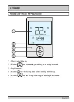
Page 3: ...M UNIT RCD3 APPEARANCE 1 2 4 3 5 1 Illuminated display 2 Button for increasing a setting or moving forward 3 Light sensor 4 Button for reviewing data and entering the setup 5 Button for reducing a setting or moving backwards ...

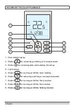
Page 4: ... entering the setup 4 Light sensor 5 Button for turning on off the room heating 6 Button for reducing a setting or moving backwards 7 Button for turning on off the Party function 8 Button for turning on off the Eco function 9 Button for turning on off the Holiday function ROOM UNIT RCD4 APPEARANCE 1 2 3 5 4 6 7 8 9 ...

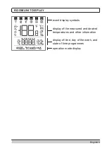
Page 5: ...nglish 5 ROOM UNIT DISPLAY event display symbols display of the measured and desired temperatures and other information display of time day of the week and state of time programmes operation mode display ...

Page 6: ...F SYMBOLS ON THE SCREEN Event display symbols Symbol Description Error See section ERROR DESCRIPTION Notification See section DESCRIPTION OF NOTIFICATIONS Low battery warning Locked buttons This symbol on the home screen means the command for remote control has been activated Data review and implementation of settings Wireless signal strength Symbol illuminated room unit in the MASTER mode Symbol ...

Page 7: ...esired nighttime temperature and Desired frost protection temperature Weather forecast sunny Weather forecast partly overcast Weather forecast overcast Weather forecast precipitation Measured indoor air quality GOOD QUALITY 0 100 symbol illuminated MEDIUM QUALITY 101 200 symbol flashing and Measured indoor air quality POOR QUALITY 201 500 both symbols flashing Premium version only Symbols for disp...

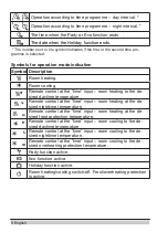
Page 8: ...ime temperature Remote control at the time input room cooling to the de sired nighttime temperature Remote control at the time input room cooling to the de sired overheating protection temperature Party function active Eco function active Holiday function active Room heating cooling switch off Frost overheating protection is active Operation according to time programme day interval Operation accor...

Page 9: ...he room temperature in addition to other information about the microclimate in the room Use the button to browse through data How much and which data we can browse through is determined with the parameters P1 10 to P1 17 With the parameter P1 18 we can configure that the home screen automatically displays the desired number of other data that we selected for reviewing the data in addition to the m...

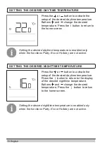
Page 10: ...bled only when the functions Party Eco or Holiday are not active SETTING THE DESIRED NIGHTTIME TEMPERATURE Press the or button to activate the setup of the desired daytime temperature Press the button to return to the display of the desired nighttime temperature Buttons and change the desired temperature Press the button to return to the home screen Setting the desired nighttime temperature is ena...

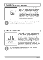
Page 11: ...perature setting is enabled only when the functions Party Eco or Vacation are not active TIME AND DATE SETTING Press the or button to activate the set up of the desired daytime temperature By pressing the button three times you move to the date display By pressing the or button and holding it for at least 2 seconds the time value starts flashing and you can change it with the buttons and Move to o...

Page 12: ...ed comfort temperature with the buttons and The value is flashing during the setup process Press the or button to move to the time setting Press the buttons and to set how long the Party function shall remain active The value is flashing during the setup process Press the or button again to return to the home screen When the Party function is active you can check or change settings by pressing the...

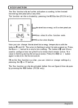
Page 13: ...s the Eco or button to move to time setting The buttons and are used to configure how long the Eco function shall remain active The value is flashing during the setup process Press the ECO or button again to return to the home screen When the Eco function is active you can check or change settings by pressing the or button The Eco function can be deactivated before the configured time elapses by p...

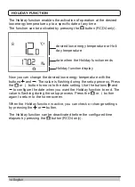
Page 14: ...s the or button to move to the date setting Use the buttons and to configure the date when you want the Holiday function to end The value is flashing during the setup process Press the or button again to return to the home screen When the Holiday function is active you can check or change settings by pressing the or button The Holiday function can be deactivated before the configured time elapses ...

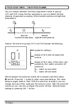
Page 15: ...ogram timer first time programme CH2 program timer second time programme t1 measured and desired temperatures d1 room unit and heating controller data P1 additional settings parameters P2 additional settings parameters S1 service settings parameters Hold the button for 2 seconds to enter the menu Move between groups of data in the menu with the buttons and Press the button to enter the selected gr...

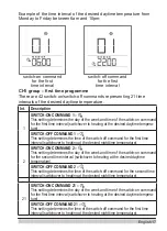
Page 16: ...s and Press the button to enter command settings The value being changed starts to flash With the switch on command you can change the days of the week and the switch on time With the switch off command you can only configure the switch off time Move between settings by pressing the button You can choose between two time programmes found in groups CH1 and CH2 Using the time programme you can defin...

Page 17: ...ommand for the second time interval switchover to heating at the desired daytime temperature SWITCH OFF COMMAND 2 This setting determines the time of the switch off command for the second time interval switchover to heating at the desired nighttime temperature 21 SWITCH ON COMMAND 21 This setting determines the day of the week and time of the switch on command for the first time interval switchove...

Page 18: ...ting determines the time of the switch off command for the second time interval switchover to heating at the desired nighttime temperature 21 SWITCH ON COMMAND 21 This setting determines the day of the week and time of the switch on command for the first time interval switchover to heating at the desired daytime tempera ture SWITCH OFF COMMAND 21 This setting determines the time of the switch off ...

Page 19: ...Move between the data or setting parameters in each group with the buttons and You can only change parameters in the groups P1 P2 and S1 The setting value starts to flash after pressing the button You can now change the parameter value with the buttons and Press the button to confirm the configured value T1 group measured and desired temperatures No Description t1 1 CONTROLLER SENSOR T1 The measur...

Page 20: ...d is displayed lux d1 17 WIRELESS SIGNAL QUALITY RSSI d1 18 NUMBER CONTROLLER ADDRESS 0 9 d1 19 PAIRING ADDRESS 0 255 d1 20 RF CHANNEL NUMBER 0 7 wireless version only P1 group additional settings parameters No Description Range P1 1 TEMPERATURE DISPLAY ROUND OFF With this setting we can determine to what value the measured temperatures should be rounded 0 0 1 C 1 0 2 C 2 0 5 C 3 1 0 C P1 2 AUTOMA...

Page 21: ...s setting determines the minimum display backlight 0 100 5 wired 0 wireless P1 6 MAXIMUM DISPLAY BACKLIGHT This setting determines the maximum display backlight 0 100 80 wired 60 wireless P1 7 DISPLAY CONTRAST This setting determines the display contrast 1 8 3 P1 8 SOUND This setting determines when the sound is activated 0 never 1 buttons 2 buttons and errors 3 buttons errors and notifications P1...

Page 22: ... displayed For browsing data use the i button Parameter P1 18 can also be used to automatically display a certain number of selected data The setting range is identical to parameter P1 11 The factory setting is 0 no display P1 15 FIFTH ADDITIONAL DISPLAY This setting determines the order of data displayed For browsing data use the i button Parameter P1 18 can also be used to automatically display ...

Page 23: ...ettings and additional functions 3 master unit additional functions P2 2 OPERATION MODE This setting determines the operation mode of the zones affected by the room unit 1 hysteresis 2 P 3 PI P2 3 ED TIME CONSTANT This setting determines the ED time constant for P and PI room temperature control 10 50min 20 P2 4 THERMOSTAT HYSTERESIS This setting determines the hysteresis for the thermostat operat...

Page 24: ...Y SENSOR CALIBRATION This setting determines the correction of the mea sured room humidity 10 10 0 S1 6 AIR PRESSURE SENSOR CALIBRATION This setting determines the correction of the mea sured air pressure 100 100mb 0 S1 7 AIR QUALITY SENSOR CALIBRATION This setting determines the correction of the mea sured air quality 100 100 0 S1 8 LIGHT SENSOR CALIBRATION This setting determines the correction ...

Page 25: ...ximum room tem perature setting possible 4 40 C 30 S1 14 ALTITUDE FOR WEATHER FORECAST This setting enters the altitude of the room unit This improves the precision of weather forecasts 0 1 999m 300 The access to service settings is locked It is possible to access locked parameters in the following way first access the S1 service parameters Now press the button and hold it for 10 seconds Use the b...

Page 26: ... Eco One time domestic hot water heating and Fireplace are also locked RCD4 only S1 10 3 same as 2 with the desired temperature settings also locked S1 10 4 same as 3 with browsing through info displays and additional service settings also locked When the buttons are locked at any stage the symbol appears in the home screen Press the button and hold it for 40 seconds to reset the parameters in gro...

Page 27: ... If this sensor is also faulty the operation is the same as that of Er1 T2 external temperature sensor error What can I do Check the type and connection of the T2 sensor on the controller If the error is not resolved the controller must be serviced The operation will automatically be adjusted as follows The controller operates without being affected by the exter nal temperature T1 supply line temp...

Page 28: ...wireless connection check the antenna connection on the controller If the error is not resolved the room unit controller and antenna must be serviced The operation will automatically be adjusted as follows After the configured time the controller switches to the so called emergency operation Controller pairing process error What can I do For the wired connection check the connection on the room un...

Page 29: ...it The room unit can also affect multiple zones at a time A zone can only be affected by one room unit If the room unit should affect the signalled zone the pairing process is activated on the room unit as well by holding the buttons and for 2 seconds During the pairing process PAIR is displayed After the pairing process is successfully com pleted a beep can be heard and the number of the zone to ...

Page 30: ...LR03 AAA batteries bus communi cation line 2 LR03 AAA batteries Maximum use 0 02W 0 06W 0 02W 0 8W Degree of protection IP 30 acc to EN 60529 IP 30 acc to EN 60529 IP 30 acc to EN 60529 IP 30 acc to EN 60529 Safety class III acc to EN 60730 1 III acc to EN 60730 1 III acc to EN 60730 1 III acc to EN 60730 1 Housing PC thermo plastic PC thermo plastic PC thermo plastic PC thermo plastic Dimensions ...

Page 31: ...collection point for waste electrical and electronic equipment WEEE Suitable disposal of this product prevents negative impact on the environment and health which could otherwise be caused by improper disposal Recycling of materials reduces usage of new raw materials For more information about recycling of this product please contact the competent authorities municipal service or the dealer where ...

Page 32: ...32 English NOTES ...

Page 33: ... English 33 NOTES ...

Page 34: ... 2019 We reserve the rights to errors changes and improvements without prior notice Software V1 3r0 V1 3 ...

Reviews: