21
Selectronic Australia
Rev 41 - Dec 2022
Installation
Before working on this circuit
Isolate uninterruptible power system (UPS)
Then check for hazardous voltage between all terminals
including the protective Earth.
Risk of voltage backfeed
Serial Port Connection
The SP PRO is fitted with a USB port and a RS232 serial port, either of which may be used to communicate
with a computer running SP LINK.
The external USB port is used to directly connect the computer to the SP PRO and enables fast, easy local
access via SP LINK software.
The RS232 port is available on the external DB9 connector or via the internal RJ45 connector. Only one of
these RS232 ports may be selected. This port is used to connect to the Select.live remote monitoring option
which, when fitted, also allows remote access via SP LINK.
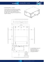
Gland Plate Fit-out
To maintain the IP rating and safety approval of the SP PRO, all gland plate holes must be
completely filled and all gland plates fitted correctly. Any gaps, including empty gland holes, are
entry points for vermin and could affect thermal performance and likely void your warranty.
Gland plates supplied with the SP PRO have knock-outs for ease of installation. Please do not knock-out any
unused gland holes and ensure all used holes have gland nuts (supplied) fitted.
Initial Start-Up Procedure
Before Turning On the SP PRO
•
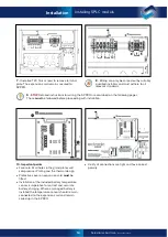
Check all connections, paying particular attention to correct polarity, tightness, and that no cable insulation
is caught in the terminals. Give each cable a firm tug to ensure it is securely fitted.
•
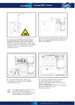
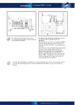
When everything is secure, attach the terminal cover plate and insert and secure the Expansion Card.
•
For SPMC1201 – SPLC1200 – SPLC1202 models: Protective cover
must
be installed on the Expansion Card.
•
Close the Battery Sense / pre-charge circuit breaker / fuses and wait until all LED indicators on the front of
the SP PRO are lit and stable.
•
Close main battery circuit breaker / fuses.
•
Having used the Site Configuration Wizard in the Easy Start Guide within SP LINK, the SP PRO must now
be configured. The SP PRO will not start until it is configured.
•
Once a configuration has been successfully loaded into the SP PRO, press the On button (long press >1
second) once. The AC Load indicator will be steady blue.
•
Start using the SP PRO by switching on external AC circuit breakers.
For SPMC1201 – SPLC1200 – SPLC1202 models: Check protective cover is installed on the
Expansion Card.
•
Replace cover and secure with two screws from below.
Labelling
Regulations mandate the application of warning and control labels to the various circuit breakers, isolators and
Switchboards in the installation. Please see relevant standards for required signage.
The SP PRO will continue to provide power to the Load upon interruption of mains supply. Warning signs must
indicate which circuits or Switchboards operate in this manner.
The installer must place a warning at the inverter terminals and isolators external to the inverter. An example
of a warning sign is shown below.
Cabling and Fusing


