


U.2.14
SEL-421/SEL-421-1 Relay
User’s Guide
Date Code 20020501
Installation
Plug-In Boards
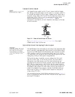
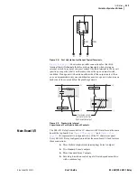
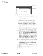
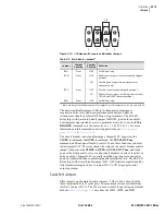
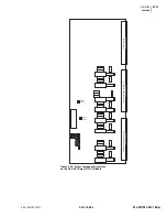
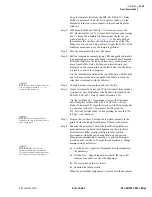
Figure 2.12
Chassis Key Positions for I/O Interface Boards.
Step 6. Install the drawout tray with I/O interface board. Use the
following precautions when installing the I/O interface board:
➤
Position the drawout tray edges into the left-side and right-side
internally mounted slots.
➤
Slide the I/O interface board into the SEL-421 Relay by
pushing the front edge of the board drawout tray.
➤
Apply firm pressure to fully seat the I/O interface board.
➤
If you encounter resistance, stop, and withdraw the board.
Inspect the drawout tray edge guide slots for damage. If you see
no damage, take all of the precautions outlined above and try
again to insert the board.
Step 7. If this is a new I/O interface board installation, remove the
INTERFACE BOARD EXPANSION SLOT self-sticking label
from the rear panel. Do this by lifting a corner of the label with
a sharp tool and peeling away the label from the rear panel.
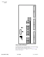
Step 8. Confirm screw terminal connector keying. SEL supplies three
new screw terminal connectors with new I/O interface boards.
Inspect the screw terminal connector receptacles on the rear of
the I/O interface board. Refer to
for
the corresponding key positions inside the receptacle. If the
keys inside the I/O Interface board receptacles are not in these
positions, grasp the key edge with long-nosed pliers to remove
the key and reinsert the key in the correct position. Break the
webs of the screw terminal connectors in the position that
matches the receptacle key (see
).
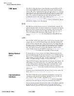
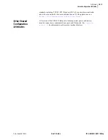
Step 9. Attach the screw terminal connector. Mount the screw terminal
connectors to the rear panel of the SEL-421 Relay. Refer to
and
for
screw terminal connector placement. Tighten the screw
terminal connector mounting screws to between 7 in-lb. and
12 in-lb. (0.8 Nm to 1.4 Nm).
Step 10. Connect the interface cable(s) from the I/O board(s) to the main
board.
Step 11. Reconnect the internal power and analog cables.
Step 12. Reattach the front panel.
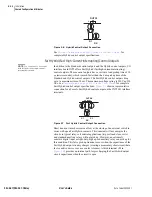
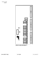
SEL-421 Relay Chassis
(Top View, Top Removed)
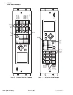
200-Addresses Keys
300-Addresses Keys
Summary of Contents for SEL-421
Page 8: ...This page intentionally left blank ...
Page 30: ...This page intentionally left blank ...
Page 110: ...This page intentionally left blank ...
Page 204: ...This page intentionally left blank ...
Page 284: ...This page intentionally left blank ...


