


U.2.40
SEL-421/SEL-421-1 Relay
User’s Guide
Date Code 20020501
Installation
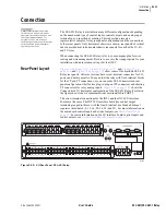
Connection
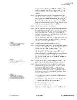
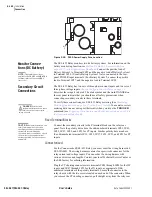
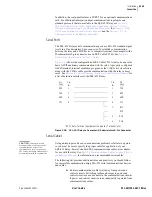
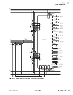
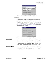
Figure 2.28
PS30 Power Supply Fuse Location.
Monitor Connec-
tions (DC Battery)
The SEL-421 Relay monitors two dc battery systems. For information on the
battery monitoring function, see
Station DC Battery System Monitor on
page A.2.22 in the Applications Handbook
. Connect the positive lead of
Battery System 1 to Terminal #Z25 and the negative lead of Battery System 1
to Terminal #Z26. (Usually Battery System 1 is also connected to the rear-
panel POWER input terminals.) For Battery System 2, connect the positive
lead to Terminal #Z27, and the negative lead to Terminal #Z28.
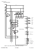
Secondary Circuit
Connections
The SEL-421 Relay has two sets of three-phase current inputs and two sets of
three-phase voltage inputs.
Shared Configuration Attributes on page 2.2
describes these inputs in detail. The alert symbol and the word DANGER on
the rear panel indicate that you should use all safety precautions when
connecting secondary circuits to these terminals.
To verify these connections, use SEL-421 Relay metering (See
Metering Quantities on page U.4.31 in the User’s Guide
). You can also review
metering data in an event report that results when you issue the
TRIGGER
command (see
Triggering Data Captures and Event Reports on page A.3.4 in
).
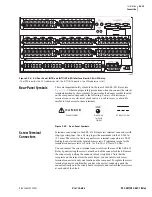
Fixed Terminal Blocks
Connect the secondary circuits to the Z terminal blocks on the relay rear
panel. Note the polarity dots above the odd-numbered terminals #Z01, #Z03,
#Z05, #Z07, #Z09, and #Z11 for CT inputs. Similar polarity dots are above
the odd-numbered terminals #Z13, #Z15, #Z17, #Z19, #Z21, and #Z23 for PT
inputs.
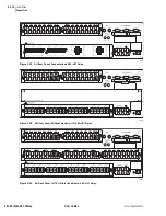
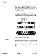
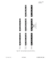
Connectorized
For the Connectorized SEL-421 Relay, you must order the wiring harness kit,
SEL-WA0421. The wiring harness contains four prewired connectors for the
relay current and voltage inputs. You can order the wiring harness with
various wire sizes and lengths. Contact your local Technical Service Center or
the SEL factory for ordering information.
Plug the CT shorting connectors into terminals #Z01 through #Z06 for the IW
inputs, and #Z07 through #Z12 for the IX inputs, as appropriate. Odd-
numbered terminals are the polarity terminals. Secure the connector to the
relay chassis with the two screws located on each end of the connector. When
you remove the CT shorting connector, pull straight away from the relay rear
J1
F1
J2
J3
Fuse
F1
NOTE:
The combined voltages
applied to the POWER and MONITOR
terminals must not exceed 600 V
(rms or dc).
DANGER:
Contact with
instrument terminals can cause
electrical shock that can result in
injury or death.
!
.
CAUTION:
Relay misoperation can
result from applying other than
specified secondary voltages and
currents. Before making any
secondary circuit connections, check
the nominal voltage and nominal
current specified on the rear-panel
nameplate.
Summary of Contents for SEL-421
Page 8: ...This page intentionally left blank ...
Page 30: ...This page intentionally left blank ...
Page 110: ...This page intentionally left blank ...
Page 204: ...This page intentionally left blank ...
Page 284: ...This page intentionally left blank ...


