


4.66
SEL-751A Relay
Instruction Manual
Date Code 20100129
Protection and Logic Functions
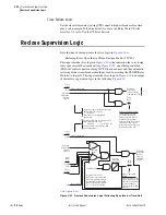
Reclose Logic
Reclosing Relay Shot
Counter
.
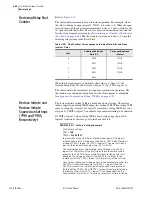
The shot counter increments for each reclose operation. For example, when
the relay is timing on open interval 1, 79OI1, it is at shot = 0. When the open
interval times out, the shot counter increments to shot = 1 and so forth for the
set open intervals that follow. The shot counter cannot increment beyond the
last shot for automatic reclosing [see
Determination of Number of Reclosures
]. The shot counter resets back to shot = 0 when the
reclosing relay returns to the Reset State.
When the shot counter is at a particular shot value (e.g., shot = 2), the
corresponding Relay Word bit asserts to logical 1 (e.g., SH2 = logical 1).
The shot counter also increments for sequence coordination operation. The
shot counter can increment beyond the last shot for sequence coordination
[see
Sequence Coordination Setting (79SEQ) on page 4.72
].
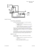
Reclose Initiate and
Reclose Initiate
Supervision Settings
(79RI and 79RIS,
Respectively)
The reclose initiate setting 79RI is a rising-edge detect setting. The reclose
initiate supervision setting 79RIS supervises setting 79RI. When setting 79RI
senses a rising edge (logical 0 to logical 1 transition), setting 79RIS has to be
at logical 1 (79RIS = logical 1) in order for open interval timing to be initiated.
If 79RIS = logical 0 when setting 79RI senses a rising edge (logical 0 to
logical 1 transition), the relay goes to the Lockout State.
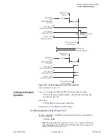
EXAMPLE 4.7
Factory Settings Example
With factory settings:
79RI :=
TRIP
79RIS :=
52A OR 79CY
the transition of the TRIP Relay Word bit from logical 0 to logical 1
initiates open interval timing only if the 52A or 79CY Relay Word bit is
at logical 1 (52A = logical 1, or 79CY = logical 1). You must assign an
input as the breaker status input (e.g., 52A := IN101).
The circuit breaker has to be closed (circuit breaker status 52A =
logical 1) at the instant of the first trip of the auto-reclose cycle in
order for the SEL-751A to successfully initiate reclosing and start
timing on the first open interval. The SEL-751A is not yet in the
reclose cycle state (79CY = logical 0) at the instant of the first trip.
Then for any subsequent trip operations in the auto-reclose cycle, the
SEL-751A is in the reclose cycle state (79CY = logical 1) and the
SEL-751A successfully initiates reclosing for each trip. Because of
factory setting 79RIS = 52A OR 79CY, successful reclose initiation in
the reclose cycle state (79CY = logical 1) is not dependent on the
circuit breaker status (52A). This allows successful reclose initiation
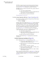
Table 4.28
Shot Counter Correspondence to Relay Word Bits and Open
Interval Times
Shot
Corresponding Relay
Word Bit
Corresponding Open
Interval
0
SH0
79OI1
1
SH1
79OI2
2
SH2
79OI3
3
SH3
79OI4
4
SH4
Summary of Contents for 751A
Page 1: ...20100129 SEL 751A Feeder Protection Relay Instruction Manual PM751A 01 NB...
Page 6: ...This page intentionally left blank...
Page 12: ...This page intentionally left blank...
Page 18: ...This page intentionally left blank...
Page 26: ...This page intentionally left blank...
Page 92: ...This page intentionally left blank...
Page 218: ...This page intentionally left blank...
Page 250: ...This page intentionally left blank...
Page 376: ...This page intentionally left blank...
Page 392: ...This page intentionally left blank...
Page 408: ...This page intentionally left blank...
Page 418: ...This page intentionally left blank...
Page 434: ...This page intentionally left blank...
Page 462: ...This page intentionally left blank...
Page 544: ...This page intentionally left blank...
Page 580: ...This page intentionally left blank...
Page 584: ...This page intentionally left blank...
Page 632: ...This page intentionally left blank...
Page 636: ...This page intentionally left blank...
Page 640: ...This page intentionally left blank...


