Version No. 1-3 - 09.11.2022
Doc. No. 99750641B001
16 / 25
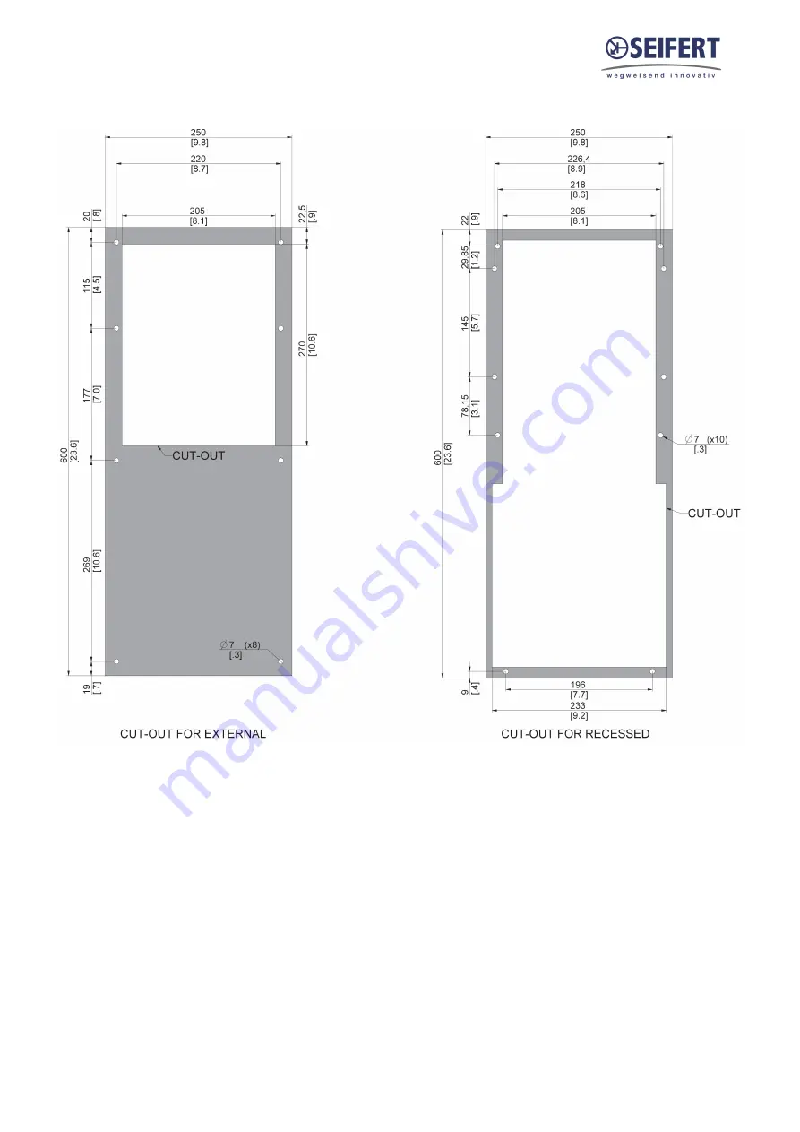
11. Cut Out Dimension
Page 1: ...ciple 6 6 Technical data 7 7 Performance graph 8 8 Mounting 9 9 Condensate management 10 10 Mounting Principle 12 11 Cut Out Dimension 16 12 Dimension H x W x D 17 13 Electrical Connection 18 14 Contr...
Page 2: ...dissipation of heat from control cabinets and enclosures stationary not moving in order to protect temperature sensitive components in an industrial environment To meet the conditions of use all the i...
Page 3: ...units based on the information diagrams or descriptions contained in this manual No liability can be accepted for damage and production caused by Disregarding the instruction manual Operating error In...
Page 4: ...y regulations One can nd dangerous voltages above 50 V AC or above 100 V DC Behind the control cabinet doors On the power supply in the unit housing The unit has to be operated according to the type p...
Page 5: ...be soft enough to avoid scale deposits but should not be too soft as this would corrode the heat exchanger Where the cooling water is cooled for reuse part of the water has to be changed with fresh w...
Page 6: ...s circulation of the air in the cabinet This circulation prevents hot spots within the control cabinet During this process the coolant heats up and is returned to the coolant supply system at an incre...
Page 7: ...sed Housing Material Mild steel powder coated Dimensions A x B x C D E 600 x 250 x 127 37 90 mm Weight 8 5 Kg Voltage Frequency 230 V 50 60 Hz Starting current 1 4 A Max current 0 35 A Max power 30 W...
Page 8: ...Version No 1 3 09 11 2022 Doc No 99750641B001 8 25 7 Performance graph...
Page 9: ...fectly sealed control cabinet will result in an increased level of condensation The control cabinet should have a minimum of IP54 protection in accordance with IEC 60 529 Cooling medium connection The...
Page 10: ...ectly through the bottom of the unit Position 2 The drain pipe must be connected wherever is most suitable for the customer application To install the drain pipe directly through the bottom of the uni...
Page 11: ...move only the lower sealing panel on the RK 7525 and RK 7555 2 Install the M5 silicon washer and the condensate drain elbow fully into the drain tting 3 Take a section of drain pipe supplied in the pa...
Page 12: ...ooling unit upright with the pre cut packaging opening facing up STEP 2 Pull o the packaging opening STEP 3 Hang the transport loop of the unit in the transport hook and lift it slightly STEP 4 Pull o...
Page 13: ...ion Ensure that ows of air leaving and entering the cooling unit internal and external are not obstructed It must also be ensured in accordance with UL that the air outlet is not blowing air directly...
Page 14: ...4 pieces Top section 1 sides 2 and bottom section 3 Attach the gasket to the unit making sure to align the holes in the gasket with the mounting popnuts Also make sure not to leave any gaps between t...
Page 15: ...ied mounting hardware Tighten Screws to 4 5 Nm Ensure the mounting surface does not warp after assembly and reinforce it if necessary 1 M6 screws 2 M6 toothed washers 3 M6 at washers 4 Enclosure 5 Mou...
Page 16: ...Version No 1 3 09 11 2022 Doc No 99750641B001 16 25 11 Cut Out Dimension...
Page 17: ...Version No 1 3 09 11 2022 Doc No 99750641B001 17 25 12 Dimension H x W x D...
Page 18: ...bridge and connect door contact switch The contact must be closed when the cabinet door is closed Alarm Contacts Alarm contacts rated according to EN60730 1 8 4 A 10 10 A 250Vac 100000 cycles UL 873 8...
Page 19: ...ord to access the protected parameters Once the parameter list is accessed PS is again displayed Press the UP or DOWN buttons to scroll through the various parameters Press SET to display the selected...
Page 20: ...Version No 1 3 09 11 2022 Doc No 99750641B001 20 25 15 Wiring Diagram Power connector PE N L1 Signal connector Door contact T2 Door contact T1 Alarm contact P2 Alarm contact P1...
Page 21: ...to scroll the numbers until displaying 22 default password to access the parameters press the SET button to con rm the password 3 Use the UP and DOWN buttons to scroll the parameters The LED correspo...
Page 22: ...fan by loosening the 4 fastening screws To detach the fan from the fan support loosen a further 4 screws and the fan connecting cable When connecting the new fan take care that the correct polarity is...
Page 23: ...ge to the unit through incorrect transport Please ensure that all liquid has been removed prior any transport To avoid transport damage the unit should be returned in the original packing or in a pack...
Page 24: ...ews M6x16 Lifting hook M8 Grommet for bottom drain position 5 pole terminal block for signals 4 pole terminal block for electrical connection Condensate drain elbow and M5 silicon washer Barbed POM el...
Page 25: ...state North Kingstown Wantirna South 42477 Radevormwald Birzebbuga BBG 3000 4563 Gerla ngen 4901 Ottnang 26100 Cremona RI 02852 3152 Victoria Germany Malta Switzerland Austria Italy USA Australia Tel...