background image

ADD ALIAS


PAGE 14


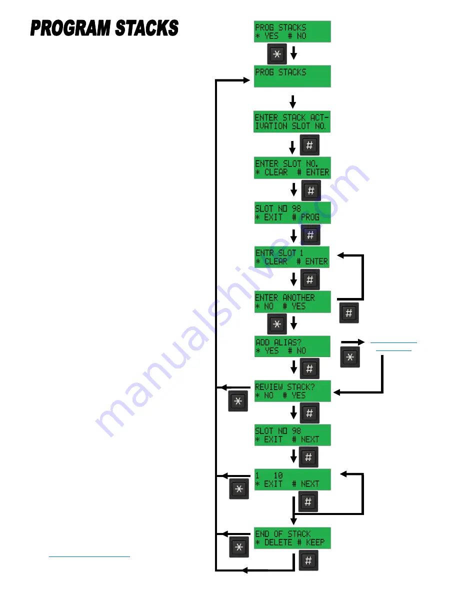
Displayed for 1.5 Sec.


Example


Slot 98


Step Through 

all of the 

Slots in the 

Stack


Displays when End 

of Stack is Reached


The Advisor will Accept up to 50 

Stacks with up to 48 Slots in each 

Stack.


Programming is Intuitive.  Just fol-

low the Screens.


Enter the Slot number that will Hold 

the Stack  (Example 98)


Press # to Accept the Slot number


Enter the Slot number for Each Slot 

in the Stack. (Maximum of 48 Slots)


Press 

“*” 

to enter a 16 character 

Alias for the Slot. (See Instructions 

on Page 25)


Press 

“#” 

to Review the Slots en-

tered into the Stack or Press 

“*” 

to 

Finish.


Display the Slot number that Holds 

the Stack.


Keep Pressing 

“#” 

to Step Through 

each Slot in the Stack.


When the End of the Stack is 

Reached you can choose to keep the 

Stack or Delete it.


ENTER UP TO 

48 SLOTS 

NUMBERS


THIS IS THE SLOT THAT 

WILL BE ENTERED TO 

PAGE THE STACK


Displayed for


 1.5 Sec.


TABLE OF CONTENTS


Summary of Contents for ADVISOR AE100

Page 1: ...ENCODER DECODER RECORDER PROGRAMMING AND INSTALLATION seinnovators com SEI ADVISOR WALL MOUNT SEI ADVISOR DESKTOP SEI RECORDER ...

Page 2: ...1 DE EMPHASIS ADD DELETE 11 SOFTWARE VERSION 12 CLEAR MEMORY 12 CONFIGURE RELAYS FOR WAKEUP SEQUENCE 12 SET WAKEUP SEQUENCE TIMEOUT 12 SETUP 13 PROGRAM ALERT RELAY 13 ADD ALIAS 14 EXIT PROGRAM 14 SCHEMATIC 15 BOARD LAYOUT 16 INSTALLATION 18 SETUP AND PROGRAMMING 22 SCHEMATIC 30 BOARD LAYOUT 31 INSTALLATION 33 ADVISOR ENCODER DECODER RECORDER ...

Page 3: ...39 ADVISOR WALL MOUNT RECEIVE ONLY 40 ADVISOR WALL MOUNT RECEIVE ONLY 40 WITH RECORDER ADVISOR WALL MOUNT ENCODER DECODER 41 ADVISOR WALL MOUNT ENCODER DECODER 41 WITH RECORDER ADVISOR WALL MOUNT ENCODER DECODER 42 WITH RECEIVER ALLOWS BASE STATION TO SCAN ADVISOR WALL MOUNT ENCODER DECODER 42 WITH RECORDER AND RECEIVER ALLOWS BASE STATION TO SCAN ADVISOR DESKTOP EXTRA ENCODER DECODER 43 WITH RECO...

Page 4: ... the Advisor is tripped It is reset with the on the Advisor key pad SEI Advisor Desktop Extra SEI Recorder Station Mobile WIFI Connectivity CLOUD Connectivity SEI Advisor Wall Mount SEI Receiver SEI Advisor Desktop ENCODING DECODING RECORDING FOR PUBLIC SAFETY TABLE OF CONTENTS ...

Page 5: ...ns Hold the key for 6 seconds to En ter the Program Mode Use the key to step through the main options Use the key to select the option press WITH NO ENTRY will return to main Program Mode menu To exit the Program Mode at any time just hold the key for 6 seconds Normal Screen Displayed for 1 5 Sec SETUP PAGE 13 DE EMPHASIS ADD DEL PAGE 11 PROGRAM ALERT RELAY PAGE 13 TABLE OF CONTENTS CONFIGURE RELA...

Page 6: ...the Digit after the Decimal Point For 1764 5 Enter 17645 Select Alert Tone for an Alert Tone to follow the Page The Slot Number will be Displayed for 1 5 Sec Tone A and Tone B will be Displayed Press to Program the Slot TO Start Again Press to enter a 16 character Alias for the Slot See Instructions on Page 25 For Group Call make the A Tone and the B Tone the Same It will now Return to Program Enc...

Page 7: ...12 A 13 B 14 C 15 D The Tones are then Displayed with the Type Press to Program the Slot Press to enter a 16 character Alias for the Slot See Instructions on Page 25 It will now Return to Program DTMF to Program another Slot if Needed Displayed for 1 5 Seconds Enter 1 8 Example 5 Enter 1 or 2 Example 1 Enter Digits One at a Time Example 3 5 9 2 8 All Digits Are Entered ADD ALIAS PAGE 14 ENTER THE ...

Page 8: ...fter the Decimal Point For 1764 5 Enter 17645 The Slot number will be Dis played for 1 5 seconds Tone A and Tone B will be Dis played Press to Program the Slot Add WAKE UP Sequence Op tion and select 1 2 or 3 Deactivate Relay Option Not Available if WAKE UP Se quence or Add Re Page are Selected It will now Return to Program Encoder to Program another Slot if Need ed Enter 1 2 or 3 Example 52 Examp...

Page 9: ...the Slot number Enter the Slot number for Each Slot in the Stack Maximum of 48 Slots Press to enter a 16 character Alias for the Slot See Instructions on Page 25 Press to Review the Slots en tered into the Stack or Press to Finish Display the Slot number that Holds the Stack Keep Pressing to Step Through each Slot in the Stack When the End of the Stack is Reached you can choose to keep the Stack o...

Page 10: ...played for 1 5 Seconds Displayed for 1 5 Seconds Display Alias Display DTMF Digits Display Alias Step Through all of the Slots in the Stack YES Return to Program Mode Displayed for 1 5 Seconds ENTER KEEP KEEP KEEP CODES 0 ALERT RELAY ONLY 2015 DEACTIVATE ALERT RELAY 20000 WAKE UP SEQUENCE 1 30000 WAKE UP SEQUENCE 2 40000 WAKE UP SEQUENCE 3 ALERT RELAY IS ACTIVE WITH WAKE UP SEQUENCE KEEP KEEP YES ...

Page 11: ...played for 1 5 Seconds Displayed for 1 5 Seconds Return to Program Mode Menu at DE EMPH ADD DEL If Transmit Audio has Pre emphasis Such as Mic Audio Add De emphasis to compensate so the Encoder Audio is Flat Displayed for 1 5 Seconds Return to Program Mode Menu at Software Ver Displayed for 1 5 Seconds Displayed for 1 5 Seconds TABLE OF CONTENTS ...

Page 12: ...Seconds YES Displayed While Clearing NO YES YES YES YES NO NO YES Displayed While Clearing NO NO Displayed for 1 5 Seconds Readout the Software Version Installed Return to Program Mode Menu at CLR MEMORY TABLE OF CONTENTS DEFAULT IS RED LIGHTS RELAY ON FOR 4 SECS THEN THE ROOM LIGHTS RELAY ON COMBINING THEM TURNS THEM BOTH ON AT THE SAME TIME ALTER THE LENGTH OF THE WAKEUP SEQUENCE RELAYS ON TIME ...

Page 13: ...SS 6 TO KEY THE RADIO AND GENERATE 8 SECONDS OF 1000 HZ PRESS 7 TO KEY THE RADIO AND GENERATE 8 SECONDS OF 2700 HZ PRESS 8 TO SEND RECEIVER AUDIO TO THE SPEAKERS EXIT YES Setup is used to Generate Tones and Set Relays so Levels can be Adjusted During Installation Displayed for 1 5 Sec The Default Operation of the Alert Relay is a 200 ms closure of the Contacts when the Advisor is Alerted This can ...

Page 14: ... Finished the is Pressed with No Entry Return to the Program Menu that it Came From Encoder DTMF or Stacks 32 SPACE 33 34 35 36 37 38 39 40 41 42 43 44 45 46 47 48 0 49 1 50 2 51 3 52 4 53 5 54 6 55 7 56 8 57 9 58 59 60 61 62 63 Example To Enter EAST GORHAM FIRE Enter 69 65 83 84 32 71 79 82 72 65 77 32 70 73 82 69 E A S T G O R H A M F I R E 64 65 A 66 B 67 C 68 D 69 E 70 F 71 G 72 H 73 I 74 J 75...

Page 15: ...TABLE OF CONTENTS ...

Page 16: ...TABLE OF CONTENTS ...

Page 17: ...TABLE OF CONTENTS ...

Page 18: ... INPUT IF THE INPUT HAS PRE EMPHASIS SUCH AS A MIC INPUT THEN SELECT DE EMPHASIS IN THE PRO GRAM MODE THE RX AUDIO IN SHOULD BE CONNECTED TO SQUELCHED AUDIO THAT DOES NOT VERY WITH THE VOLUME CONTROL THE SEI RECEIVER CONNECTS TO RX AUDIO IN AUTOMATICALLY WHEN PLUGGED IN SERIES WITH THE ADVISOR SEE PAGE 18 GROUND RX AUDIO IN IF NOT USING DECODER TX AUDIO IN IF NO GOOD CONNECTION FOR TX AUDIO OUT IS...

Page 19: ... HIGH RF ENVIRONMENTS Cat 5 Cable is run to the Equipment Room to connect to the PA Amplifier The Lights can be Controlled Remotely through the Building Wiring using PULSE WORX Wall Switch Receivers Receiver Modules and Transmitter Modules Transmitter Unit Uses the Relay Contacts from the Advisor to Activate Deactivate the Wall Switches or the Plug in Modules Wall Switch gets a Signal from the Tra...

Page 20: ...QUELCHED AUDIO THAT DOES NOT VERY WITH THE VOLUME CONTROL GROUND RX AUDIO IN IF NOT USING THE DECODER FUNCTION OF THE ADVISOR 1 _ FEED A 2850HZ TONE INTO THE RECEIVER AT 94DBM 2 _ ADJUST RX AUDIO IN CLOCKWISE UNTIL THE DISPLAY JUST STARTS TO FLASH RECEIVING AUDIO ADJUST BACK AND FORTH TO BE SURE IT IS JUST ON THE EDGE OF STARTING TO FLASH RECEIVING AUDIO 3 _ TURN RX AUDIO IN CLOCKWISE 1 FULL TURN ...

Page 21: ... THE RADIO MOUNTING THE UNIT IN A MOBILE INSTALLATION THE ENCODER HAS FOUR THREADED INSERTS ON THE BOTTOM OF THE HOUSING THE INSERTS MATCH UP WITH THE STANDARD AMPS PATTERN ON A PEDESTAL MOUNT DO NOT USE SCREWS LONGER THEN 1 4 OR THE BOARD WILL BE DAMAGED PEDESTAL MOUNT 1 4 MOUNTING SCREWS TABLE OF CONTENTS ...

Page 22: ... INSTALLATION INSTRUCTIONS REBOOT THE RECORDER BY UNPLUGGING AND PLUGGING BACK IN FROM A COMPUTER WITH WIFI OR A WIFI ADAPTOR FIND THE seirecorder NETWORK ACCESS POINT AND CONNECT TO IT WITH THE PASS PHRASE seirecorder123 TABLE OF CONTENTS ...

Page 23: ...P PASSWORD AND THE IP AD DRESS IF YOU WANT TO SELECT Network OPEN A BROWSER ENTER THE URL http 192 168 50 1 configure SIGN IN TO BRING UP THE CONFIGURATION PAGE USER NAME admin PASSWORD seirecorder123 OPEN THE DROP DOWN LIST THE WHEEL WILL SPIN WHILE THE SYSTEM IS WORKING TABLE OF CONTENTS ...

Page 24: ...ECORDER WILL DISCONNECT CLOSE THE BROWSER REBOOT BY UNPLUGGING AND PLUGING IN THE RECORDER RECONNECT WITH THE NEW NAME OPEN A BROWSER ENTER THE URL http 192 168 50 1 configure SELECT Audio TABLE OF CONTENTS ...

Page 25: ...THE RED LINES 1 YOU CAN CLICK ON THE SLIDER AND USE THE ARROW KEYS ADJUST THE VOX LEVEL 8 SO ANY SYSTEMIC NOISE DOES NOT EXTEND OVER THE GREEN LINES 3 MIC AND REC AUDIO CAN BE GATED 4 W HIGH OR LOW OUTPUTS 5 EXAMPLE A COR OR A CTCSS DECODE CAN GATE THE REC AUDIO A PTT LEVEL CAN GATE THE MIC AUDIO ADVISOR SLAVE 6 IF CHECKED THE RECORDER ONLY RECORDS WHEN THE ADVISOR IS TRIPPED ADVISOR RELAY MUST BE...

Page 26: ...PARTMENT CAN BE DISPLAYED WHEN THE ENTRY CONTAINING THE TONES IS CLICKED EACH DEPARTMENT CAN HAVE A DIFFERENT COLOR ENTRY ENTER TONE A TONE B THE DEPARTMENT NAME AND THE HEX CODE OR THE OFFICIAL NAME FOR THE COLOR SEE htmlcolorcodes com CP THE LOWEST NUMBER WILL DETERMINE THE COLOR DISPLAYED IF IT IS IN A STACK OF TONES TABLE OF CONTENTS ...

Page 27: ...OUD SERVICES ARE CHOSEN THEN 3 KEYS WILL BE EMAILED TO YOU EACH KEY MUST BE COPIED AND PASTED INTO THE CORRECT BOX THEN SET ONE AT A TIME THE WHEEL WILL SPIN WHILE THE KEY IS BEING SET SELECT Cloud TABLE OF CONTENTS ...

Page 28: ... Network CHOOSE YOUR SYSTEM FROM THE DROP DOWN MENU OF AVAILABLE WIFI SSIDs ENTER THE PASSPHRASE FOR YOUR NETWORK CLICK ADD THE RECORDER WILL NOW DISCONNECT AND REBOOT CONNECT TO WIFI SYSTEM TABLE OF CONTENTS ...

Page 29: ...LL SCROLL DOWN TO THE BOTTOM OF Wifi Status PAGE AND YOU CAN SEE THE CONFIGURED NETWORKS MORE WIFI NETWORKS CAN BE ADDED AFTER REBOOT THE ACCESS POINT MODE IS ACTIVE FOR 45 MINS YOU CAN ALWAYS ACCESS IT DIRECTLY FROM A CELL PHONE OR A WIFI COMPUTER USING 192 168 50 1 IF YOU HAVE NOT CHANGED IT IN MOBILE UNITS THE ACCESS POINT MODE IS AVAILABLE ALL THE TIME THE RECORDER IS AWAY FROM THE WIFI SYSTEM...

Page 30: ...TABLE OF CONTENTS ...

Page 31: ...TABLE OF CONTENTS ...

Page 32: ...TABLE OF CONTENTS ...

Page 33: ...WITH AN INLINE CONNECTOR IS PROVIDED TO CONNECT TO THE BACK OF THE MIC JACK IN THE RADIO SO THE CONTROL HEAD CAN STILL BE REMOVED IF TX AUDIO IS HARD TO CONNECT TO IN THE RADIO THEN A MODULAR MIC JUNCTION BOX CAN BE USED TO PICK UP THE MIC AUDIO IF THE MIC HAS A MODULAR CONNECTOR PAGE 18 5 POWER RED B 12 15VDC 6 GROUND BLK GROUND 7 OPTIONAL RX AUDIO GATE ORG IF NO SQUELCHED AUDIO IS AVAILABLE THEN...

Page 34: ...nd etc can be Picked Up in the Junction Box and Run Back to the Recorder Mic Audio It can be Difficult to get Mic Audio from the Radio A Jumper is Included with the Recorder so Mic Audio can be picked up from the back of the Mic Jack on the Control Head and run to the back of the Radio for Connection to the Recorder An inline Connecter is part of the Jumper so the Control Head can be Removed TABLE...

Page 35: ... ADAPTOR CONSIDERATIONS _SOME MICROPHONES DO NOT GATE THE AUDIO WITH THE PTT IF THE MIC AUDIO FROM THIS MIC IS CONNECTED TO THE RECORDER ALL OF THE AUDIO NEAR THE MIC WILL BE RECORDED _ YOU DON T WANT THIS _THE RECORDER CAN GATE THE MIC AUDIO WITH A PTT INPUT GOING LOW MUST BE PROGRAMMED ON THE CONFIGURATION SCREEN _A PTT INPUT ON THE ACC CONNECTOR WILL NOT NECESSARILY GO LOW WITH A RADIO MIC PTT ...

Page 36: ...TABLE OF CONTENTS ...

Page 37: ...TABLE OF CONTENTS ...

Page 38: ...TABLE OF CONTENTS ...

Page 39: ...TABLE OF CONTENTS ...

Page 40: ...7 TABLE OF CONTENTS ...

Page 41: ...TABLE OF CONTENTS ...

Page 42: ...TABLE OF CONTENTS ...

Page 43: ...TABLE OF CONTENTS ...

Page 44: ...TABLE OF CONTENTS ...

Page 45: ...TABLE OF CONTENTS ...

Page 46: ...ar from the date of purchase Damage due to misuse or modification is not covered under this warranty The unit must be returned to the factory and we will repair or replace it at our option at no charge SMART EQUIPMENT INNOVATORS LLC 603 447 3925 info seinnovators com seinnovators com 220710A TABLE OF CONTENTS ...

Reviews: