background image

v2.0  11/8/11 

36 

Tour Between Points 


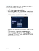
Multiple  preset  points  can  be  connected  to  create  “tour  lines”.  The  PTZ  camera  can  be 
programmed to cruise a set of presets along a specified line. 
 

a.  Using the direction control buttons move the camera to a desired point. 

b.  Click the 

SET

 button on the 

PTZ Control

 interface screen. 

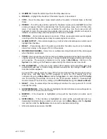
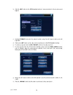
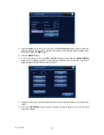
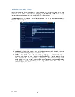
c.  Using the screen below as an example, click the 

TOUR

 button, and use the left mouse 

button  and  soft  keyboard  to  enter  the  preset  point  and  the  tour  line  number  (

PATROL 

NO.

). Then click 

ADD PRESET

d.  To  set  the  interval  or  dwell  time  (time  the  camera  will  remain  on  a  preset  point  before 

moving to the next point) enter the desired value in the 

INTERVAL

 field. 


e.  Repeat the above steps until all presets are added for each tour line (Patrol Line) under 

Tour. 

f.  To remove a preset, enter the preset value and click the 

DEL PRESET

 button. 

g.  To remove a tour line, enter the Patrol No. value and click the 

DEL TOUR

 button. 

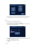
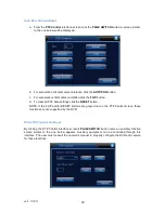
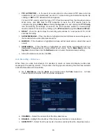
h.  To call a tour from the PTZ Control interface screen click the 

PAGE SWITCH 

button once 

to  display  a  page  for  calling  presets,  patterns,  tours,  and  scans.  The  control  page 
displayed will be similar to the one below. 


Summary of Contents for ST-DVR8716BG

Page 1: ...v2 0 11 8 11 1 USER MANUAL ST DVR8716BG 16 Channel Digital Video Recorder ...

Page 2: ...RATION 14 1 POWERING ON and SHUTTING DOWN 14 Powering On 14 Shutting Down 14 2 ACCESSING SYSTEM MENU 15 3 USER ACCESS RIGHTS 15 4 PREVIEW MODE 16 5 MAIN MENU 16 6 RECORDING OPERATION 18 Manual Recording 18 Auto Recording 19 Auto Recording Motion Detection Recording 20 Auto Recording Video Blind 23 Auto Recording Video Loss 24 Auto Recording Alarm Recording 26 7 PLAYBACK OPERATION 28 8 BACKING UP R...

Page 3: ... 52 User Account Management 53 Online User 55 Output Adjust 55 Auto Maintain 56 Restore Defaults 56 Upgrade 57 Device Information 58 12 SYSTEM INFORMATION 58 Hard Disk Information 58 Code Stream Statistics 59 Log Information 59 Edition Information 60 13 MISCELLANEOUS FUNCTIONS and SETTINGS 61 Disk Event 61 Color Settings 61 REMOTE MANAGEMENT USING CLIENT SOFTWARE 63 1 CMS SOFTWARE INSTALLATION 63 ...

Page 4: ...ce network in residences offices banks warehouses factories prisons or any environment requiring surveillance monitoring Important Notes The DVR s embedded PTZ controller is designed to perform a wide variety of PTZ camera control functions However the utility of any PTZ controller is highly dependant upon the particular PTZ camera to be controlled as each camera has not only its own functions but...

Page 5: ...ction Areas Multiple Sensitivity Levels 15 Storage 2pcs SATA HDD up to 2TB or 1 SATA HDD and 1 DVD R W 16 Backup Network USB DVD 17 HDD Capability Channel Audio 28 8Mbytes hr Video 25 450Mbytes hr 18 Controller Front Panel Buttons Remote Controller USB Web 19 Operating System Linux 20 Image Display Full Screen 1 4 8 9 16 Split 21 Network Port RJ45 10M 100M Adaptive Ethernet Network Port 22 PTZ Con...

Page 6: ...his DVR is for indoor use only and must be installed in a safe ventilated and dry area c Open the DVR case only to install the hard drive s There are no serviceable parts inside the unit d If liquids spill inside the DVR s case immediately turn off all power to the unit disconnect the unit from its power source and have a qualified technician check it for damage e Do not install the DVR in an envi...

Page 7: ...nitoring device to the DVR s RCA A OUT port d To control a PTZ camera using the DVR s embedded PTZ controller use the DVR s RS485 A and B connections A is positive B is negative Be sure the polarities are correct and consistent with the camera You may also use the RS485 AB connections for an external PTZ controller e If the DVR is to be networked for remote monitoring and or management connect the...

Page 8: ...u have an existing hard drive you wish to use with the DVR you may install it at your own risk and determine if the DVR recognizes the drive and correctly records data to it If you are considering the purchase of a hard drive contact Securitytronix for recommended manufacturers and models h Connect the included power supply to the DVR s power port Then plug the power supply to an appropriate AC ou...

Page 9: ...NO or NC 2 Ground 3 Alarm Output Normally Open and COM 4 RS485 communications A B b The alarm input has no restriction i e normal can be either open or close c The alarm input is a grounding alarm input The grounding of the power supply and the alarm sensor must be shared when using an external power supply d The GND alarm detector is connected to the alarm sensor s COM via a parallel connection e...

Page 10: ...Resistance Load Rating Maximum Switch Current 1A Contact to Contact 1000VAC for 1 minute Contact to Coil 1000VAC for 1 minute Isolation Interface and Winding 1000VAC for 1 minute Surge Voltage 1500VAC 10x160us Turn on Time Turn off Time 3ms Maximum 3ms Maximum Mechanical 50x106 MIN 3Hz Longevity Electrical 200x103 MIN 0 5Hz Environmental Temperature 40 F 158 F ...

Page 11: ...ht cursor key and pan right under PTZ Control 10 ENTER Power On button Enter function 11 DOWN Down cursor key and pan down under PTZ Control 12 LEFT Left cursor key and pan left under PTZ Control 13 USB Port USB Port for backup drive or flash drive 14 MENU Provides access for logging into the system and Main Menu 15 ESC Exit a function or operation 16 QUAD Select from 1 4 and 16 window monitor dis...

Page 12: ...d toolbar II Rewind video playback Up Down Left and Right direction buttons MENU Provides access to the DVR s main menu OK OK serves as an Enter key ZOOM ZOOM Camera zoom in and out under PTZ Control 1 0 Numeric keys PTZ Displays the PTZ Control window BACK Exit an operation or function same as an ESC key DEV If using multiple DVRs select DVR1 DVR2 FN Assist function for PTZ Control and Color Sett...

Page 13: ...y a short cut menu for select DVR functions The Short cut Menu is similar to the one displayed below Main Menu Calls up the Main Menu Record Mode Calls up the Record Mode Screen Play Back Calls up the playback interface for playback control PTZ Control Calls up the PTZ Control Interface HighSpeed PTZ Calls up the High Speed Control Interface Alarm Output Calls up the Alarm Output screen Color Sett...

Page 14: ...ECTED message will be displayed If no hard drive is installed power down the DVR install the hard drive and turn on the DVR The system will then detect the drive and request to format if necessary If a hard drive is installed but the DVR issues the not detected message i the hard drive could be faulty and require replacement and or ii the power and SATA cable connections between the hard drive and...

Page 15: ...cess menus and make menu selections will depend upon the user s access rights as described below 3 USER ACCESS RIGHTS There are 2 default access settings from the factory Admin Top authority with all privileges permissions Guest Privileges permissions limited to preview and video playback Admin and User privileges permissions cannot be changed However their passwords can be modified In addition th...

Page 16: ...annel Camera lock current user login does not have rights to view that channel 5 MAIN MENU The Main Menu provides user access to all DVR functions and operations This section will highlight each Main Menu function with detailed operational instructions provided in subsequent sections Accessing the Main Menu can be done by pressing MENU on the DVR s front panel or by clicking on the Right Mouse But...

Page 17: ...iew display Main Menu Sub Menu Description Record Config Set the recording configuration recording type time session Playback Playback a recorded file Includes file search capability by record mode channel time etc Record Backup Detect or format backup storage backup selected files Motion Detection Configure and or change video motion detection settings Video Blind Configure and or change video bl...

Page 18: ...R audio in alarm in alarm out configuration HDD Info Hard disk capacity and free space View recording times Code Stream Statistics Display code stream statistics Log Information Select and display various log data System Information Edition Information DVR serial number software version build date etc Shutdown User logout DVR shutdown and DVR reboot 6 RECORDING OPERATION Manual Recording a Right c...

Page 19: ...initial boot Detection Allows automatic recording when the camera detects motion in a given area the camera is blinded or there is video signal loss Alarm Allows the automatic recording when an external event triggers an alarm e g a door opening The setting of automatic recording conditions per channel is done via the Record Config screen Go to Main Menu click the Record icon then the Record Confi...

Page 20: ...eo loss event The video file type is M Alarm Recording is triggered by an external alarm The video file type is A h Upon completing all desired settings click SAVE Note If the recording configuration requires Detection Motion Detection Video Blind or Video Loss and or Alarm additional settings must be made under the Alarm Menu by going to Main Menu and clicking the Alarm icon Auto Recording Motion...

Page 21: ... motion detection region position the mouse cursor on a block click the right mouse button and drag the mouse over the area to be defined Use the left mouse button to de select Right click the mouse button and select UpWindow from the pop up menu and return to the Motion Detection setup screen f PERIOD To set the day and time period for the motion detection function to take place click SET and a s...

Page 22: ...vated and set to automatically pan and or cruise among pre determined spots By clicking on SET a PTZ Activation screen similar to the one below appears For each PTZ camera select the type of PTZ function desired from the drop down menu When done click OK Note for PTZ activation to work the PTZ camera has to be configured by going to Main Menu clicking the System icon and clicking the PTZ Config ic...

Page 23: ...n menu or ALL for the entire week Four possible time slots are available for each day Use the mouse and soft keyboard to enter the required time periods Upon doing so the graphic will adjust to indicate the selected days and time periods When done click OK f ALARM OUTPUT If an external signal e g bell is to be activated upon a video blind event highlight the checkbox g DELAY Period during which th...

Page 24: ...n the monitor when a video blind event occurs m BUZZER If the checkbox is highlighted a beep will be heard when a video blind event occurs n SEND EMAIL If the checkbox is highlighted an email will be automatically sent to a designated individual when a video blind event occurs Go to Main Menu click the System icon and then click the NetService icon to enter the desired email setting o After all se...

Page 25: ...icon and entering the interval period in seconds i PTZ ACTIVATION In the event of a video loss or other alarm a PTZ camera can be activated and set to automatically pan and or cruise among pre determined spots By clicking on SET a PTZ Activation screen appears For each PTZ camera select the type of PTZ function desired from the drop down menu When done click OK Note for PTZ activation to work the ...

Page 26: ...n similar to the one below will be displayed b Three alarm output settings are available Configuration The alarm is on according to the configuration Manual Click the ALL button and the corresponding channel will record when an alarm is sensed regardless of other settings Stop Click to stop channel alarming regardless of the channel s state c Configure the Alarm Input by going to Main Menu clickin...

Page 27: ... which the alarm took place If desired additional single windows per channel will sequence The sequence interval is set by going to Main Menu clicking on the System icon clicking on the Tour icon and entering the interval period in seconds m PTZ ACTIVATION In the event of an alarm a PTZ camera can be activated and set to automatically pan and or cruise among pre determined spots By clicking on SET...

Page 28: ... on the DVR s front panel Upon doing so a PlayBack File Search screen similar to the one below will appear NOTE Icon 4 for file backup will not appear on screen until a search has been performed which finds at least one file b To locate a file for playback click the File Search icon 3 Doing so will display a Search Condition screen with the following search options or criteria 1 Listed Video Files...

Page 29: ... system to automatically play all files that satisfy the search criteria c If individual files are to be played back click the checkbox for the desired files displayed in the Listed Files area 1 of the Playback File Search screen d Using the Playback Toolbar click the Play icon or other controls to manage the file Icon Description Icon Description II Playback and pause Repeat playback Play backwar...

Page 30: ...ppears d Upon clicking the Backup icon a Playback Backup screen similar to the one below will be displayed e Install a backup storage device such as USB flash drive The DVR should automatically detect the device If not click the DETECT button The detected device will appear in the list box on the top portion of the screen Select the desired device by highlighting the device s checkbox ERASE erases...

Page 31: ...n followed by the Backup icon A Record Backup screen similar to the one below will appear b Install a backup storage device such as USB flash drive The DVR should automatically detect the device If not click the DETECT button The detected device will appear in the list box on the top portion of the screen If more than one backup device is listed select the desired device by highlighting the device...

Page 32: ... PTZ controller is designed to perform a wide variety of PTZ camera control functions However the utility of any PTZ controller is highly dependant upon the particular PTZ camera to be controlled as each camera has not only its own functions but specific methods of how those native functions are accessed and managed Further a particular PTZ controller s terminology may differ from that used by a p...

Page 33: ...down box select the DVR channel the PTZ camera is on c In the PROTOCOL drop down box select the PTZ camera s protocol e g PELCOD d In the ADDRESS field input the PTZ camera s device ID e g 1 e In the BAUD RATE drop down box select the PTZ camera s baud rate f In the DATA BIT STOP BIT and PARITY drop down boxes select the parameters that match those for the PTZ camera Defaults are respectively 9600...

Page 34: ...l cameras support remote iris adjustment e DIRECTION CONTROL Control the camera s pan and tilt by clicking on any one of the 8 direction arrows f PAGE SWITCH Clicking this button presents consecutive pages for setting up PTZ camera presets scans tours etc g SET Provides access to a screen for creating presets used in PTZ camera tours patterns and border scan h PTZ TRACE Clicking this buttion displ...

Page 35: ...e PTZ Control interface e To remove a preset click the DEL PRESET button on the above screen f To call a preset from the PTZ Control interface screen click the PAGE SWITCH button once to display a page for calling presets patterns tours and scans The control page displayed will be similar to the one below g Using the left mouse button and soft keyboard enter the desired preset number to be called ...

Page 36: ...ne number PATROL NO Then click ADD PRESET d To set the interval or dwell time time the camera will remain on a preset point before moving to the next point enter the desired value in the INTERVAL field e Repeat the above steps until all presets are added for each tour line Patrol Line under Tour f To remove a preset enter the preset value and click the DEL PRESET button g To remove a tour line ent...

Page 37: ...be controlled to repeatedly scan tour lines a Click the SET button on the PTZ Control interface screen b Using the screen below as an example click the PATTERN button and use the mouse and soft keyboard to input the pattern value c Click BEGIN Doing so will return to the PTZ Control interface screen where zoom focus iris direction etc adjustments can be made d Click SET on the PTZ Control interfac...

Page 38: ...e desired pattern number to be called h Click the PATTERN button and the camera will travel along the configured line Border Scan A scan between preset left and right positions is possible a Using the direction buttons on the PTZ Control interface screen move the camera to the desired left boundary point Click the SET button on the PTZ Control interface screen b Using the screen below as an exampl...

Page 39: ...k the RIGHT button e To call a border scan from the PTZ Control interface screen click the PAGE SWITCH button once to display a page for calling presets patterns tours and scans The control page displayed will be similar to the one below f Using the left mouse button and soft keyboard enter the desired border scan number to be called g Click the AUTOSCAN button and the camera will travel between t...

Page 40: ...lear all PTZ data settings click the RESET button NOTE If the FLIP and or RESET buttons are grayed out on the PTZ Control screen those functions are not supported by the DVR Other PTZ Control Functions By clicking the PTZ Control interface screen s PAGE SWITCH button twice an auxiliary function screen similar to the one below appears Auxiliary equipment can be controlled through this interface The...

Page 41: ... and clicking on the System icon Upon doing so the System Sub menu will appear General Settings Go to Main Menu click on the System icon then the General icon General settings include system time and date date format and separator time format language hard drive full management options video format etc The General menu screen displayed is similar to the one below a SYSTEM TIME Position the mouse c...

Page 42: ... disk becomes full the DVR can either overwrite the hard disk or stop recording Select the desired option from the drop down menu h DVR NO Assign a DVR address for the infrared remote Used when the remote is to control multiple DVRs i VIDEO STANDARD From the drop down menu select either NTSC or PAL Use NTSC for operation in the U S A j AUTO LOGOUT If desired for security purposes the DVR can autom...

Page 43: ...64 is the only compression and cannot be changed c RESOLUTION Resolution types are CIF QIF d FRAME RATE Selectable from 1 to 30 FPS using the drop down menu e BIT RATE TYPE Select VBR variable bit rate or CBR constant bit rate from the drop down menu When selecting VBR six image quality options are provided f QUALITY Six levels of video quality are available from the drop down menu g BIT RATE Kb S...

Page 44: ...s 255 255 255 0 The Gateway default address is 192 168 1 1 The Gateway allows access to the network and often is the same address as the network router The DNS IP address is provided by the ISP Once the address is set the DVR must be rebooted A DNS is not often necessary See the network administrator regarding the specifics for setting the DNS c TCP PORT Default is 34567 Note 34567 is assigned for...

Page 45: ...PPPoE is a specification for connecting the users by Ethernet to the Internet through a common broadband medium PPPoE generally involves the use of a DSL modem or cable modem If PPPoE is to be used the IP address account name and password are required The system must be rebooted after saving After the reboot the DVR will automatically setup the PPPoE network connection and the ISP will modify auto...

Page 46: ... PERIOD Default is 10 minutes d EMAIL An email can be sent to a designated recipient in the event an alarm event has taken place Note the DVR must be configured to identify an alarm caused by motion detection video loss physical contact etc The Email configuration screen is similar to the one below Highlight the ENABLE checkbox SMTP SERVER Use the mouse cursor left mouse button and soft keyboard t...

Page 47: ...n creating an IP address black list the listed IP addresses cannot connect to the DVR 64 bit IP addresses are supported on both white and black lists If an IP address is on both the white and black list the black list takes precedence The IP Filter configuration screen is similar to the one below Highlight the ENABLE check box f DDNS Dynamic Domain Name Server DDNS permits a DDS name to be synchro...

Page 48: ... snapshot picture are uploaded to a FTP server NOTE if the DVR does not support the snapshot feature the FTP function will not work Highlight the ENABLE checkbox SERVER IP Input the IP address for the FTP server PORT Input the Domain Port of the FTP server The default is 21 USER NAME Input the FTP server s user name PASSWORD Input the user s password MAX FILE LENGTH Specifies the maximum length of...

Page 49: ...The DVR support the UPNP protocol to allow the DVR to appear as a plug and play network device UPNP must be running on the network router before implementing it on the DVR A UPNP configuration screen similar to the one below will be displayed Highlight the ENABLE checkbox HTTP The router will automatically distribute the HTTP port for the DVR when using Internet Explorer for viewing TCP The router...

Page 50: ... be displayed f TRANSPARENCY Using the slider set the level of GUI transparency over the background image Range is 128 to 255 g RESOLUTION Using the drop down menu select one of five display resolutions h CHANNEL Using the drop down menu select the set code output channel number i e camera DVR channel i REGION COVER If desired a region in the camera s image can be blacked out Highlight the Region ...

Page 51: ...e below will appear a INTERVAL Using the mouse cursor left mouse button and soft keypads enter the sequence interval timing Range is 5 to 120 seconds b VIEW View 1 refers to single window display Highlight the channel numbers for channels to be displayed View 4 refers to a quad display where 4 channel windows will be displayed at one time View 8 provides two quad displays of 4 channel windows per ...

Page 52: ...e drive READ ONLY No data can be written to the disk REDUNDANCY Double backup the video files to a ReadWrite disk Note a second hard drive is required FORMAT DISK Hard drives need to be formatted to operate with the DVR If a hard drive is not formatted it will not be recognized by the DVR Generally all hard drives newly installed in the DVR will have to be formatted On occasions there may be a nee...

Page 53: ...acters are letters numbers underline minus sign and dot The maximum password length is 6 characters Users can be assembled as a group The group name and a user name cannot be the same Further a user can belong only to one group a MODIFY USER Clicking this button displays the Modify User screen where group permissions and other attributes can be changed b MODIFY GROUP Clicking this button displays ...

Page 54: ...the Add Group screen where the group name is created and group permissions are set f DELETE USER Clicking this button deletes a user once a confirmation is made g DELETE GROUP Clicking this button displays a Delete Group screen for removing a particular group ...

Page 55: ...s From Main Menu click the Advanced icon followed by the Online User icon An Online User screen similar to the one below will be displayed Output Adjust The monitor s borders can be adjusted using the Output Adjust feature From Main Menu click the Advanced icon followed by the Output Adjust icon or by clicking the right mouse button select Output Adjust from the Short cut Menu The Output Adjust sc...

Page 56: ...ld files From Main Menu click the Advanced icon followed by the AutoMaintain icon The displayed AutoMaintain screen is similar to the one below Restore Defaults To restore the DVR settings to the factory defaults from Main Menu click the Advanced icon followed by the Restore icon The displayed Restore screen is similar to the one below ...

Page 57: ...o the DVR for download to the unit NOTE If a DVD burner is installed upgrading must be done via the network From the Main Menu click the Advanced icon followed by the Upgrade icon The displayed Upgrade screen is similar to the one below a UPGRADE POSITION Using the drop down menu select the source of the upgrade file e g USB port b UPGRADE FILE Using the drop down menu select the specific folder a...

Page 58: ...nnels Alarm In Channels Alarm Out Channels and SD Card Record 12 SYSTEM INFORMATION Hard Disk Information From Main Menu click the System Information icon followed by the HDD Info icon The HDD Info screen displays hard drive s location s i e position 1 and or 2 hard drive type e g read write disk capacity remaining capacity and status The user may also view recording times per disk ...

Page 59: ...d by the Code Stream Statistics icon The display is updated in real time Log Information From Main Menu click the System Information icon followed by the Log Information icon A Log information screen similar to the one below will appear Log message types include system configuration storage alarm event weekday account and playback ...

Page 60: ... left mouse button and soft keyboards to enter the desired date and time c Click the SEARCH button d NEXT PAGE If the list of log messages exceeds a page click the NEXT PAGE button e REMOVE To delete all log messages click the REMOVE button Edition Information Hardware and software version numbers build date and serial number can be viewed by going from Main Menu clicking the System Information ic...

Page 61: ... BUZZER To notify the user of the abnormal event highlight the desired checkboxes to display a message and or activate a buzzer d When done click the SAVE button Color Settings For each channel display window it is possible to customize the color brightness contrast saturation hue and gain settings Further these settings can be set fixed or set for two user defined time periods This can be used fo...

Page 62: ...time periods b SETTINGS SLIDER Using the mouse cursor and left mouse button drag the slider s to the desired position c ADVANCED By clicking the Advanced button a pop up menu appears with the following options UpWindow return Show Desktop return to preview mode Cold Color Warm Color and Default Color By selecting Warm Cold or Default Color the sliders will self adjust d When done click OK ...

Page 63: ...s of Remote Management Client software a Center Manager System CMS and b Super NetSurveillance SNS Functionally both are very similar It may be a matter of personal preference which software is selected 1 CMS SOFTWARE INSTALLATION To install the software on a Microsoft Windows PC a Place the included CD in the PC s CD or DVD drive and run A screen similar to the one below will appear b Click the S...

Page 64: ...tion for the application files If acceptable click NEXT or enter an alternate location and click NEXT e A Select Program Folder dialog box appears displaying a default Program Folder name If acceptable click NEXT or select an alternate name and click NEXT f A series of screens will appear as part of the software installation g Click the Center Manager System application icon to launch the applicat...

Page 65: ...me there is no password to login Simply click OK CONFIGURING and USING THE CMS CLIENT a After successful login the DVR Client application icon the DVR remote screen similar to the one below will appear b Click on the SYSTEM bar in the lower right corner The Device Manager screen will appear ...

Page 66: ...f the screen d An Edit entry box will appear Enter the device name IP address port number user name and user password Note the IP address and port number should be the same as configured under the Network setup on the DVR User name and password must already be registered in DVR under Accounts When done click OK ...

Page 67: ...the left side of the screen Double click the device name Shortly thereafter the DVR s camera channel list will be displayed and the screen transitions to Monitor Mode Connection status will be displayed in the center bottom portion of the screen Note If connection to the DVR is to be made over the Internet a Virtual Private Network VPN connection may be necessary to direct the remote management so...

Page 68: ...ter lower portion of the screen h For PTZ camera control click the PTZ bar in lower right portion of the screen Using the PTZ controls on the right side of the screen the camera can be panned tilted and zoomed Focus and iris adjustments are possible as well Note For the PTZ control function to work the PTZ camera s must be configured with the DVR either through the DVR s PTZ configuration setup me...

Page 69: ...e the desired adjustments j To Record position the cursor into the camera window to be recorded Click the right mouse button and a pop up menu will appear with the following selections Close Window Close All Windows Audio Local Record Snapshot Device Config Select Local Record and the recording process will begin To stop recording return to the pop up menu and deselect Local Record ...

Page 70: ...PC i e the PC running CMS For example C Program Files CMS Picture The user may select the desired storage area by clicking the System bar clicking the Local Config icon and entering the relevant information drive directory sub directory see I System Settings and Configuration below k To Search for and Playback files click the Search bar in the lower right portion of the screen Upon doing so a Sear...

Page 71: ...n will appear Specific local files can be backed up by clicking the Local Playback tab performing a file search highlighting the file s and clicking the BACKUP button l System Settings and Configurations The CMS software allows for both local based PC settings as well as remote setting of the DVR To begin click the System bar in the lower right portion of the screen Icons for the following will ap...

Page 72: ...v2 0 11 8 11 72 The Alarm Setting tab provides for Alarm I O Trigger Video Motion Detection Video Blind and Video Loss alarm settings ...

Page 73: ...v2 0 11 8 11 73 ...

Page 74: ...nput o System Setup General Encode Network NetService CAM Name and PTZ Config o Advanced Account AutoMaintain and Default o Info HDD Info Log and Version The settings process using CMS is very similar to using the DVR s menus When done with each setting be sure to click OK or APPLY to save the configuration A sample of one of the Remote Config screens is below ...

Page 75: ...v2 0 11 8 11 75 Account Users can be added and deleted User passwords can be modified User groups can also be added and deleted Sample Account screens are below ...

Page 76: ...messages Log message types include Operation and Alarm messages o Operation Messages Types Video Playback Backup User Manager Map Client Config Device Config and System Operation o Alarm Message Types I O Trigger Video Motion Video Loss Video Blind Disk Error and Disk Full ...

Page 77: ...r to the one below will appear The folder contains the following software CMS remote management software SNS Super NetSurveillance remote management software Player A video file player Active X plug in Mobile Monitor Software for remote DVR access and management using Symbian and Microsoft Windows Mobile Smartphones This software has not been field tested Video Converter Tool Video file converter ...

Page 78: ...an alternate location and click NEXT e A Select Program Folder dialog box appears displaying a default Program Folder name If acceptable click NEXT or select an alternate name and click NEXT f A series of screens will appear as part of the software installation g Click the Super NetSurveillance application icon to launch the application It s advisable to place the SNS application icon on the deskt...

Page 79: ...d USING THE SNS CLIENT a After successful login the DVR Client application icon the DVR remote screen similar to the one below will appear b A Device Management screen will also appear If not click the next to Device As no DVR is yet connected to the SNS client it will be necessary to add a device Click ADD on the Device Management screen ...

Page 80: ...er password and channel number Note the IP address and port number should be the same as configured under the Network setup on the DVR User name and password must already be registered in DVR under Accounts When done click OK The Device Management screen will then be updated with the new device information ...

Page 81: ...v2 0 11 8 11 81 d The SNS screen will now have the new device name under the Device List on the right side of the screen e By double clicking on the Device Name the DVR s camera channels will be listed ...

Page 82: ...v2 0 11 8 11 82 f Double clicking on cameras on the list will display the camera channel ...

Page 83: ...ra control click the PTZ button on the upper right side of the screen Using the PTZ controls on the right side of the screen the camera can be panned tilted and zoomed Focus and iris adjustments are possible as well Note For the PTZ control function to work the PTZ camera s must be configured with the DVR either through the DVR s PTZ configuration setup menu or through the SNS system configurator ...

Page 84: ...0 11 8 11 84 i To adjust the image color contrast or brightness in any given channel window click the Color button in the upper right side of the screen and use the sliders to make the desired adjustments ...

Page 85: ...Path screen will appear identifying where the local recording file will be stored on the PC Click OK To stop recording return to the pop up menu and deselect Local Record k To take a Snapshot of an image position the mouse cursor in the camera window click the right mouse button and select Snapshot from the pop up menu Upon doing so a Change Path screen will appear identifying where the local imag...

Page 86: ...nus to locate the file Files will appear in a list window To play those files highlight the appropriate checkboxes and click the Play button Use the screen s Playback toolbar to control the playback To save them to the local PC highlight the checkboxes and click the Download button A dialog box will appear and provide a file name for saving the file in the SNS Download folder ...

Page 87: ... the Playback toolbar A dialog window will appear listing files saved on the PC in the SNS Download folder Select the desired file click the Open button and the recording will play in the Playback screen n To adjust Local Settings click the Local Config button and a Config Manager screen will appear ...

Page 88: ...v2 0 11 8 11 88 Alarm settings and alarm linkages can be created using the Alarm Setting screens ...

Page 89: ...v2 0 11 8 11 89 User passwords can be modified via the User Manager screen The System Settings screen is limited to the option of allowing auto connect to the last monitoring channel ...

Page 90: ...v2 0 11 8 11 90 The About screen displays SNS version information ...

Page 91: ...onfiguration of the DVR s settings for o Recording o Alarms Video Motion Video Blind Video Loss and Alarm Input o System Setup General Encode Network NetService CAM Name and PTZ Config o Advanced Account AutoMaintain Default and Reboot o Info HDD Info Log and Version The settings process using SNS is very similar to using the DVR s menus When done with each setting be sure to click OK or APPLY to ...

Page 92: ...v2 0 11 8 11 92 ...
Reviews: