background image

23

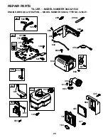
REPAIR PARTS

TILLER - - MODEL NUMBER 944.621534

ENGINE, BRIGGS & STRATTON - - MODEL NUMBER 126302, TYPE NO. 0206-E1

20

22

12

21

306

1058 OWNER’S MANUAL

1019 LABEL KIT

15

1

307

415

3

718

552

18

1022

40

1034 1029

45

1026

13

337

635

5

914

383

868

619

1022

914A

40

35

238

11

33

34

1023

146

16

741

24

46

746

742

32

30

29

27

28

220

219

27

25

26

36

830

192

32A

122

51

7

993

15A

155

332

914B

1330 REPAIR MANUAL

Summary of Contents for 944.621534

Page 1: ...es and Instructions Before Operating This Equipment MODEL NO 944 621534 OWNER S MANUAL Assembly Operation Maintenance Service and Adjustments Repair Parts 5 5 HP 24 INCH TINE WIDTH FRONT TINE TILLER S...

Page 2: ...the controls and the proper use of the equipment Know how to stop the unit and disengage the controls quickly Never allow children to operate the equipment Never allow adults to operate the equipment...

Page 3: ...CENTRE DEPARTMENT FOR SPARK ARRESTER REFER TO THE REPAIR PARTS SECTION OF THIS MANUAL FOR PART NUMBER TABLE OF CONTENTS SAFETY RULES 2 CUSTOMER RESPONSIBILITIES 3 PRODUCT SPECIFICATIONS 3 WARRANTY 3 A...

Page 4: ..._7 FRONT LEFT RIGHT OPERATOR S POSITION FIG 1 Your new tiller has been assembled at the factory with exception of those parts left unassembled for shipping purposes To ensure safe and proper operation...

Page 5: ...rely Cut away carton Route tine control cable s through plastic cable clip on handle mount NOTE Cables must not touch the muffler Cut cable ties securing tiller to skid Remove tiller from skid by pull...

Page 6: ...ROTTLE CONTROL RECOIL STARTER HANDLE OPERATION DEPTH STAKE Controls forward speed and the depth at which the tiller will dig RECOIL STARTER HANDLE Used to start the engine KNOW YOUR TILLER READ THIS O...

Page 7: ...h stake should always be below the wheels for digging It serves as a brake to slow the tiller s forward motion to enable the tines to penetrate the ground Also the more the depth stake is lowered into...

Page 8: ...See Fig 7 With engine level remove engine oil filler plug Fill engine with oil to point of overflowing For approx imate capacity see PRODUCT SPECIFICATIONS on page 3 of this manual Tilt tiller back on...

Page 9: ...climate rainfall and wind it may be advisable to till the soil at the end of the growing season to further condition the soil Soil conditions are important for proper tilling Tines will notreadilypen...

Page 10: ...eensubjectedtooperatorabuseornegligence Toreceive fullvaluefromthewarranty theoperatormustmaintaintiller as instructed in this manual Some adjustments will need to be made periodically to properly mai...

Page 11: ...LOWER HOUSING CYLINDER FINS AIR CLEANER CARTRIDGE AIR CLEANER SCREW COVER FIG 13 TEMPERATURE RANGE ANTICIPATED BEFORE NEXT OIL CHANGE SAE VISCOSITY GRADES 20 0 30 40 80 100 30 20 0 20 30 40 F C 32 10...

Page 12: ...ling conditions Handle height will be different when tiller digs into soil If a higher handle height is desired loosen the four nuts securing handle panel to engine brackets Slide handle panel to desi...

Page 13: ...control cable is too tight which is extending lower spring and engaging tines Loosen cable clip and push down on cable only enough to relieve spring tension Tighten cable clip Recheck in OFF position...

Page 14: ...Fig 21 Replace V belt if it has stretched considerably or if it has cracks or frayed edges Belt guard must be removed to service belt See TO RE MOVE BELT GUARD in this section of manual BELT REMOVAL R...

Page 15: ...Inspect and replace belts if necessary See belt re placement instructions in the Service and Adjustments section of this manual Lubricate as shown in the Maintenance section of this manual Be sure tha...

Page 16: ...Stale or dirty fuel 6 Drain fuel tank and refill with fresh gasoline 7 Water in fuel 7 Drain fuel tank and carburetor and refill tank with fresh gasoline 8 Clogged fuel tank 8 Remove fuel tank and cl...

Page 17: ...Control Tine 20 154805 Pin Pivot KEY PART NO NO DESCRIPTION 1 38 3 3 18 21 19 20 29 35 35 36 13 12 50 14 handle_assy_99_9 NOTE All component dimensions given in U S inches 1 inch 25 4 mm REPAIR PARTS...

Page 18: ...55 Spacer Split 523 x 718 x 2 0 9 165768X558 Guard Belt 10 109227X Pad Idler 11 9484R Clip Cable 12 9180R V Belt 13 12000028 Ring Retainer 14 151223 Sheave Transmisison 16 12000036 Ring Klip 17 STD541...

Page 19: ...Hairpin 8 1952J Support Depth Stake R H 9 122233X Stake Depth 10 326J Pin Clevis 11 74780628 Bolt Hex 3 8 16 x 1 3 4 13 1951J Support Depth Stake L H 15 5388J Spring Stake 16 121117X Bolt Shoulder 17...

Page 20: ...2 tine_ipb_3 KEY PART NO NO DESCRIPTION 4 156923 Tine Inner L H 5 156925 Tine Outer L H 6 4929H Pin Clevis 1 156926 Tine Outer R H 2 3146R Retainer Spring Zinc 3 156924 Tine Inner R H REPAIR PARTS TI...

Page 21: ...16 18 x 1 1 2 Gr 2 2 STD523732 Bolt Fin Hex 3 8 16 x 3 1 4 3 STD551037 Washer 13 32 x 13 16 x 11 5 STD541437 Locknut w washer 3 8 16 6 9056R558 Shield Tine 7 188195 Bracket Engine R H 8 165834 Bracke...

Page 22: ...cal Tire Shield 5 137283 Decal Cntrl Pnl Inst 6 110614X Decal Hand Placement 8 162384 Decal Tine Shield Warning 9 171078 Decal Rewind Intek 10 167156 Decal B S Intek 11 120076X Decal Warning Rotating...

Page 23: ...O 0206 E1 20 22 12 21 306 1058 OWNER S MANUAL 1019 LABEL KIT 15 1 307 415 3 718 552 18 1022 40 1034 1029 45 1026 13 337 635 5 914 383 868 619 1022 914A 40 35 238 11 33 34 1023 146 16 741 24 46 746 742...

Page 24: ...TYPE NO 0206 E1 108 130 95 127 51 104 137 276 276 134 133 975 117 186 692 122 51 365 125 98 121 CARBURETOR OVERHAUL KIT 104 137 127 633A 633 134 137 633 977 CARBURETOR GASKET SET 51 633A 122 51 20 3 7...

Page 25: ...4 621534 ENGINE BRIGGS STRATTON MODEL NUMBER 126302 TYPE NO 0206 E1 334 851 333 209 663 562 505 227 616 209A 632 836 836A 190 832 676 677 300 883 613 615 356 601 187 222 773 188 621 427 271 668 504 28...

Page 26: ...621534 ENGINE BRIGGS STRATTON MODEL NUMBER 126302 TYPE NO 0206 E1 1022 7 1095 VALVE GASKET SET 51 868 993 332 23 363 455 1005 1070 1036 EMISSIONS LABEL 55 456 58 60 459 689 597 608 1211 1210 48 1329...

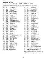
Page 27: ...188 Kit Needle Seat 137 693981 Gasket Float Bowl 146 690979 Key Timing KEY PART NO NO DESCRIPTION 155 698214 Plate Cylinder Head 161 699207 Base Air Cleaner 163 696024 Gasket Air Cleaner 186 692317 Co...

Page 28: ...Cover Top 914B 697551 Screw Rocker Cover Center 957 694261 Cap Fuel Tank 968 692584 Cover Air Cleaner 971 690370 Screw Air Cleaner Base 972 694260 Tank Fuel 975 493640 Bowl Float 977 697001 Gasket Set...

Page 29: ...29 SERVICE NOTES...

Page 30: ...30 SERVICE NOTES...

Page 31: ...31 SERVICE NOTES...

Page 32: ...PRINTED IN THE U S A 192373 03 26 04 TR 02488...

Reviews: