background image

19

SERVICE AND ADJUSTMENTS

FRONT-TO-BACK ADJUSTMENT (See Figs. 21 and 22)

IMPORTANT:  DECK MUST BE LEVEL SIDE-TO-SIDE. IF
THE FOLLOWING FRONT-TO-BACK ADJUSTMENT IS
NECESSARY, BE SURE TO ADJUST BOTH FRONT LINKS
EQUALLY  SO  MOWER  WILL STAY LEVEL SIDE-TO-
SIDE.

To obtain the best cutting results, the mower housing should
be adjusted so that the front is approximately 1/8" to 1/2"
lower than the rear when the mower is in its highest position.

FIG. 22

NUT “E”

BOTH FRONT LINKS MUST BE EQUAL IN LENGTH

TRUNNION

“D”

“D”

FIG. 21

NUT “F”

FRONT LINKS

MANDREL

TO LEVEL MOWER HOUSING

Adjust the mower while tractor is parked on level ground or
driveway.  Make sure tires are properly inflated (See “PROD-
UCT SPECIFICATIONS” section of this manual).   If tires are
over or underinflated, you will not properly adjust your
mower.
SIDE-TO-SIDE ADJUSTMENT (See Figs. 19 and 20)

Raise mower to its highest position.

At the midpoint of both sides of mower, measure height
from bottom edge of mower to ground.   Distance “A” on
both sides of mower should be the same or within 1/4"
of each other.

If adjustment is necessary, make adjustment on one
side of mower only.

To raise one side of mower, tighten lift link adjustment
nut on that side.

To lower one side of mower, loosen lift link adjustment
nut on that side.

NOTE: Each full turn of adjustment nut will change mower
height about 1/8".

Recheck measurements after adjusting.

BOTTOM EDGE
OF MOWER TO
GROUND

FIG. 19

SUSPENSION
ARM

LIFT LINK
ADJUSTMENT NUT

FIG. 20

A

A

GROUND LINE

BOTTOM EDGE

OF MOWER TO

GROUND

Check adjustment on right side of tractor.  Measure distance
“D” directly in front and behind the mandrel at bottom edge
of mower housing as shown.

Before making any necessary adjustments, check that
both front links are equal in length.  Both links should be
approximately 10-3/8".

If links are not equal in length, adjust one link to same
length as other link.

To lower front of mower loosen nut “E” on both front links
an equal number of turns.

When distance “D” is 1/8" to 1/2" lower at front than rear,
tighten nuts “F” against trunnion on both front links.

To raise front of mower, loosen nut “F” from trunnion on
both front links. Tighten nut “E” on both front links an
equal number of turns.

When distance “D” is 1/8" to 1/2" lower at front than rear,
tighten nut “F” against trunnion on both front links.

Recheck side-to-side adjustment.
Summary of Contents for 944.600051

Page 1: ...RACTOR Caution Read and follow all Safety Rules and Instructions Before Operating This Equipment MODEL NO 944 600051 OWNER S MANUAL Assembly Operation Customer Responsibilities Service and Adjustments...

Page 2: ...stability of the machine Keepallmovementontheslopesslowandgradual Do not make sudden changes in speed or direction Avoid starting or stopping on a slope If tires lose traction disengage the blades an...

Page 3: ...n the machine Tall grass can hide obstacles Useslowspeed Choosealowgearsothatyouwillnot have to stop or shift while on the slope Avoid starting or stopping on a slope If tires lose traction disengage...

Page 4: ...al or state laws if any If a spark arrester is used it should be maintained in effective working order by the operator A spark arrester for the muffler is available through your nearestSearsAuthorized...

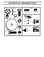
Page 5: ...Lock washer 3 8 Steering Wheel Insert Steering Extension Shaft Steering Sleeve Steering Wheel Steering Wheel Adapter 1 Knob 1 Washer 17 32 x 1 3 16 x 12 Gauge Seat 1 Shoulder Bolt 5 16 18 Battery 2 K...

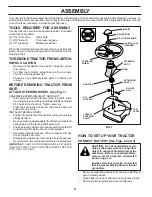
Page 6: ...mbled at the factory with exception of those parts left unassembled for shipping purposes To ensure safe and proper operation of your tractor all parts and hardware you assemble must be tightened secu...

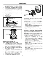
Page 7: ...y release clutch brake pedal and slowly drive tractor off skid Apply brake to stop tractor set parking brake and place gearshift lever in neutral position Turn ignition key to OFF position Continue wi...

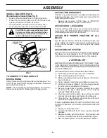
Page 8: ...e factory for shipping purposes Correct tire pressure is important for best cutting performance Reduce tire pressure to PSI shown in PRODUCT SPECIFICATIONS section of this manual CHECK DECK LEVELNESS...

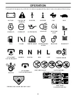
Page 9: ...RD FAST SLOW ENGINE ON ENGINE OFF OIL PRESSURE LIGHTS ON FUEL CHOKE MOWER HEIGHT PARKING BRAKE LOCKED UNLOCKED REVERSE NEUTRAL HIGH LOW ATTACHMENT CLUTCH ENGAGED MOWER LIFT DANGER KEEP HANDS AND FEET...

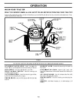
Page 10: ...the engine PARKINGBRAKE Locksclutch brakepedalintothebrake position GEARSHIFT LEVER Selects the speed and direction of the tractor ATTACHMENT LIFT LEVER Used to raise lower and adjustthemowerdeckoroth...

Page 11: ...brake will shut off the engine Depress clutch brake pedal into full BRAKE position andhold Place parking brake lever in ENGAGED position and releasepressurefromclutch brakepedal Pedalshould remain in...

Page 12: ...actor at more than five 5 MPH TO START ENGINE See Fig 6 Whenstartingtheengineforthefirsttimeoriftheenginehas run out of fuel it will take extra cranking time to move fuel from the tank to the engine S...

Page 13: ...n The best time to mow your lawn is the early afternoon At this time the grass has dried and the newly cut area will not be exposed to the direct sun Forbestresults adjustthemowercuttingheightsothat t...

Page 14: ...bolt to 35 ft lbs maximum Do not overtighten 1 12 3 2 5 5 6 7 GENERAL RECOMMENDATIONS The warranty on this tractor does not cover items that have beensubjectedtooperatorabuseornegligence Toreceive fu...

Page 15: ...ngine Whentheengineisrunningandtheattachmentclutchis engaged any attempt by the operator to leave the seat should shut off the engine Theattachmentclutchshouldneveroperateunlessthe operator is in the...

Page 16: ...o your expected operating temperature Whenoperatingintemperaturesbelow0 F 18 C synthetic oil must be used CAUTION Air cooled engines run hotter than automotive engines Theuseofnon syntheticmulti visco...

Page 17: ...G 17 FUEL FILTER CLAMP CLAMP FOAM PRE CLEANER COVER KNOB COVER CARTRIDGE NUT FIG 16 PAPER CARTRIDGE BASE AIR FILTER See Fig 16 Yourenginewillnotrunproperlyusingadirtyairfilter Clean the foam pre clean...

Page 18: ...spring slide collar off and push housing guide out of bracket Disconnect anti swaybar from chassis bracket by re movingretainerspring Disconnect suspension arms from rear deck brackets by removing re...

Page 19: ...is necessary make adjustment on one side of mower only To raise one side of mower tighten lift link adjustment nut on that side To lower one side of mower loosen lift link adjustment nut on that side...

Page 20: ...redistancebetweenbrakeoperatingarmandnut A on brake rod If distance is other than 1 1 2 loosen jam nut and turn nut A untildistancebecomes1 1 2 Retightenjamnut against nut A Road test tractor for prop...

Page 21: ...elhuband axle Insert square key Replace washers and snap retaining ring securely in axle groove Replace axle cover NOTE To seal tire punctures and prevent flat tires due to slow leaks tire sealant may...

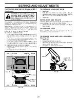
Page 22: ...uel tank and battery TO REMOVE CABLES REVERSE ORDER BLACK cable first from chassis and then from the fully chargedbattery RED cable last from both batteries SERVICE AND ADJUSTMENTS NEGATIVE TERMINAL P...

Page 23: ...valve in clockwise de creases the supply of fuel to the engine giving a leaner fuel airmixture Turningtheidlemixturevalveout counterclock wise increasesthesupplyoffueltotheenginegivingaricher fuel ai...

Page 24: ...G IN ESSENTIAL FUEL SYSTEM PARTS SUCH AS CARBURETOR FUEL FILTER FUEL HOSE OR TANK DURING STORAGE ALSO EXPERIENCE INDICATES THAT ALCOHOL BLENDED FUELS CALLED GASOHOL OR USING ETHANOL OR METHANOL CAN AT...

Page 25: ...ty ignition switch 7 Check replace ignition switch 8 Faulty solenoid or starter 8 Check replace solenoid or starter 9 Faulty operator presence switch es 9 Contact an authorized service center departme...

Page 26: ...mowing 4 Mower deck not level 4 Level mower deck 5 Low uneven tire air pressure 5 Check tires for proper air pressure 6 Worn bent or loose blade 6 Replace sharpen blade Tighten blade bolt 7 Buildup o...

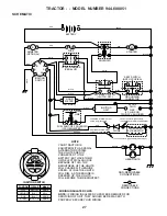
Page 27: ...UR TRACTOR IS EQUIPPED WITH A SPECIAL ALTERNATOR SYSTEM THE LIGHTS ARE NOT CONNECTED TO THE BATTERY BUT HAVE THEIR OWN ELECTRICAL SOURCE BECAUSE OF THIS THE BRIGHTNESS OF THE LIGHTS WILL CHANGE WITH E...

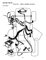
Page 28: ...28 REPAIR PARTS TRACTOR MODEL NUMBER 944 600051 ELECTRICAL 28 29 26 24 42 43 27 27 25 41 27 27 40 33 30 52 D C AMPERES 45 16 16 8 2 1 27 22 21...

Page 29: ...56 24 4799J Cable Battery 6 Ga 11 red 25 146147 Cable Battery 6 Ga w 16 wire red 26 166180 Fuse 15 AMP 27 73510400 Nut Keps Hex 1 4 20 UNC 28 4207J Cable Ground 6 Ga 12 black 29 121305X Switch Plunger...

Page 30: ...MODEL NUMBER 944 600051 CHASSIS AND ENCLOSURES 64 74 60 30 51 57 53 52 54 55 17 29 28 12 3 31 1 3 2 9 208 207 208 5 5 144 25 26 26 10 26 144 25 26 60 3 3 3 142 208 13 208 11 143 60 3 3 3 142 37 18 20...

Page 31: ...SupportFender 37 17490508 Screw Thdrol 6 16 18 x 1 2 TYT 38 169834 Bracket Asm Pivot Mower Rear 51 73800400 Nut Lock Hex W Ins 1 4 20 52 19091416 Washer 9 32 x 7 8 x 16 Ga 53 145201 Bracket Grille Pic...

Page 32: ...51 74 75 78 76 77 1 25 19 24 2 53 35 34 37 36 35 62 36 64 65 59 56 51 72 55 63 116 70 77 61 22 27 26 6 113 18 51 5 18 6 85 52 30 32 32 30 52 11 85 80 4 3 13 81 84 82 145 79 16 96 26 89 90 27 51 48 15...

Page 33: ...105710X Link Clutch 55 105709X Spring Return Clutch 6 75 56 STD523712 Bolt Fin Hx 3 8 16 X 1 1 4 57 130801 V Belt Ground Drive 58 127274X Keeper Belt RH LT Pnt zinc 16g 59 169691 Keeper Belt Span Ctr...

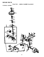
Page 34: ...944 600051 STEERING ASSEMBLY 82 22 5 9 5 7 7 9 4 3 32 43 6 43 8 18 19 27 62 23 11 40 66 29 25 79 8 10 40 11 8 6 9 46 46 8 6 9 2 47 47 1 41 17 42 37 36 37 26 30 28 38 63 11 39 44 51 54 80 68 67 67 67...

Page 35: ...7 8 X 16 Ga 29 17060612 Screw 3 8 16 x 3 4 30 STD561210 Pin Cotter 1 8 X 3 4 Cad 32 130465 Rod Tie Wire Form 19 75 Mech 36 155099 Bushing Strg 37 152927 Screw 38 139769 Insert Cap Strg Wh Au 39 19133...

Page 36: ...155925 Pan Seat 11 166369 Knob Seat 12 121246X Bracket Mounting Switch KEY PART NO NO DESCRIPTION 13 121248X Bushing Snap Blk Nyl 50 Id 14 72050412 Bolt Rdhd Sqnk 1 4 20x1 1 2 15 134300 Spacer Split...

Page 37: ...Sealant Tire 10 oz Tube 12 8 20 14 7 1 156369 Decal Fend STLT Oper 2 163207 Decal Fender S D W H T Rad 3 171696 DecalHoodRH 4 171697 Decal Hood LH 6 146046 Decal V Belt Drive Sch 7 163252 Decal Dash...

Page 38: ...38 REPAIR PARTS TRACTOR MODEL NUMBER 944 600051 ENGINE 2 1 OPTIONAL EQUIPMENT Spark Arrester 29 44 46 32 31 33 37 33 40 62 13 4 72 78 81 3 14 38 15 16 78 23 45...

Page 39: ...ree 3 8 18 Npt 16 STD551237 Washer Lock Ext Tooth 3 8 23 169837 ShieldBrowning 29 137180 ArrestorSpark 31 109202X Tank Fuel 1 25 Fr 32 158990 Cap Asm Fuel W sym Vented 33 123487X Clamp Hose Blk 37 137...

Page 40: ...37 30 31 32 33 146 148 145 150 45 144 147 147 142 149 142 35 49 50 51 54 52 53 55 56 34 1 46 44 21 22 24 25 26 27 2 28 29 23 21 21 21 18 18 20 2 48 59 19 4 3 129 92 131 130 92 5 6 21 40 143 36 40 37...

Page 41: ...sher 13 32 x 13 16 x 16 Gauge 40 STD541437 Nut 44 140088 Guard Mandrel LH 45 STD624003 Retainer 46 137729 Screw Thdrol 1 4 20 x 5 8 T 48 133944 Washer Hardened 49 155066 Roller Assembly Cam Follower 5...

Page 42: ...42 REPAIR PARTS TRACTOR MODEL NUMBER 944 600051 MOWER LIFT 15 20 16 1718 20 20 15 20 4 5 6 2 3 1 6 5 4 7 8 12 11 31 32 31 32 19 19 13 13 13 13...

Page 43: ...9 ID 7 125631X GripHandleFluted 8 122365X Button Plunger 11 139865 Link Lift Lh Fixed Length 12 139866 Link Lift Rh Fixed Length 13 STD624008 RetainerSpring 15 173288 Link Front 16 73350800 Nut Jam He...

Page 44: ...44 REPAIR PARTS TRACTOR MODEL NUMBER 944 600051 PEERLESS TRANSAXLE MODEL NUMBER 206 545C...

Page 45: ...nged Bushing 5 8 ID 35A 780197 Flanged Bushing 751 36 790075 Brake Disk 37 790007 Brake Pad Plate 38 799021 Brake Pad pkg of 2 39 786026 Dowel Pin 40 792076A Flat Washer 312 ID x 059W REF PART NO NO D...

Page 46: ...238 1026 1029 40 40 868 45 35 830 1022 13 5 33 34 192 27 26 27 32 25 28 29 24 146 16 741 757 761 46 43 54 50 1022 383 337 635 1023 914 307 306 REQUIRES SPECIAL TOOLS TO INSTALL SEE REPAIR INSTRUCTION...

Page 47: ...RBURETOR OVERHAUL KIT 137 276 95 104 105 137 276 142 634 987 127 977 CARBURETOR GASKET SET 117 106 231 267 216 232 222 188 209 265 202 REQUIRES SPECIAL TOOLS TO INSTALL SEE REPAIR INSTRUCTION MANUAL T...

Page 48: ...PE NUMBER 0136 E1 363 1006 1005 75 934 1044 23A 1051 783A 695 165 726 23 304 732 37 78 305 727 1036 LABEL EMISSIONS 318 544 802 801 803 310 697 311 729 1051 309 510 1090 579 783 513 462 1051 513 783A...

Page 49: ...lywheel Guard 93 690602 Bushing Throttle Shaft 94 498030 Valve Idle Adjustment 95 691636 l Screw Throttle Valve 98 495800 Kit Idle Speed 104 690525 l Pin Float Hinge KEY PART NO NO DESCRIPTION 105 231...

Page 50: ...cluded in Value Overhaul Kit Ref Number 1033 NOTE All component dimensions given in U S inches 1 inch 25 4 mm KEY PART NO NO DESCRIPTION 310 690323 Screw Starter Motor 311 497608 Brush Set 318 692127...

Page 51: ...DE ONLY RIDE UP AND DOWN HILL NOT ACROSS HILL SUGGESTED GUIDE FOR SIGHTING SLOPES FOR SAFE OPERATION Operate your Tractor up and down the face of slopes not greater than 15 never across the face Make...

Page 52: ...ny Sears Canada Inc Service Centre Department and most Retail Stores WHEN ORDERING REPAIR PARTS ALWAYS GIVE THE FOLLOWING INFORMATION PRODUCT TRACTOR MODEL NUMBER 944 600051 ENGINE MODEL NUMBER 310707...

Reviews: