background image

Summary of Contents for 1F80-382

Page 1: ...d air conditioning contractor or electrician Do not exceed the specification ratings All wiring must conform to local and national electrical codes and ordinances This control is a precision instrument and should be handled carefully Rough handling or distorting components could cause the control to malfunction To prevent electrical shock and or equipment damage disconnect electric power to system...

Page 2: ...ull the cover straight off the base Forcing or prying on the thermostat will cause damage to the unit If necessary move the electric heat switch see ELECTRIC HEAT SYSTEMS above 2 Connect wires beneath terminal screws on base using appropriate wiring schematic see figs 2 through 7 3 Place base over hole in wall and mark mounting hole locations on wall using base as a template 4 Move base out of the...

Page 3: ...ed when the system switch is in the HEAT position JUMPER JUMPER WIRE WIRE T mpressorll t an I I ntact r Re _ 1 24 wc TRANSFORMER Figure 7 Typical wiring diagram for heat pump with reversing valve energized in HEAT The 24 Volt neutral connection to terminal C on the thermostat is not required if the batteries are replaced once a year with fresh premium brand alkaline batteries Heating System 1 Move...

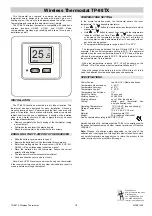
Page 4: ...e run program mode then press PRGM and RUN atthe same time to enter the configuration menu The display will show the first item in the configuration menu The configuration menu table summarizes the configuration options An explanation of each option follows Figure 8 Thermostat display buttons and switches Press HOLD to change to the next menu item or press TIME to go backwards to the previous item...

Page 5: ... This is intended to help protect the compressor from short cycling Some newer compressors already have a time delay built in and do not require this feature Your compressor manufacturer can tell you if the feature is already present in their system When the com pressor time delay occurs it will flash the snowflake icon for about five minutes then turn on the compressor 7 Select Temperature Displa...

Page 6: ... 70 F 5 00 PM 70 F 5 00 PM 70 F 4TH 10 00 PM 62 F 10 00 PM 62 F 10 00 PM 62 F 1ST 6 00 AM 78 F 6 00 AM 78 F 6 00 AM 78 F 2ND 8 00 AM 85 F 8 00 AM 85 F 8 00 AM 85 F O O 3RD 5 00 PM 78 F 5 00 PM 78 F 5 00 PM 78 F 4TH 10 00 PM 82 F 10 00 PM 82 F 10 00 PM 82 F Enter Heating Program 1 Move the SYSTEM switch to HEAT 2 Press PRGM once MO TU WE TH FR indicating week day program will appear in the display ...

Page 7: ... Furnace power switch to OFE 3 Furnace blower compartment door or panel loose or not properly installed 1 Pilot light not lit 2 SYSTEM Switch not set to H EAT 3 Loose connection to thermostat or system 4 Furnace Lock Out Condition Heat may also be intermittent 5 Heating System requires service or thermostat thermostat requires replacement 1 SYSTEM Switch not set to COOL 2 Loose connection to therm...

Page 8: ...of your system or service person can instruct you on how to test the Heat Cool system for correct operation If the system operates correctly replace the thermostat Item 2 in the Configuration Menu is the adjustment that controls the cycle rate If an acceptable cycle rate is not achieved using the FA Fast or SL Slow adjustment contact a local service person for additional suggestions The cycle rate...

Reviews: