BODYSHOP/WORKSHOP HEADLAMP
BEAM SETTER
Model no:
HBS2001
Thank you for purchasing a Sealey product. Manufactured to a high standard, this product will, if used according to these
instructions, and properly maintained, give you years of trouble free performance.
IMPORTANT:
PLEASE READ THESE INSTRUCTIONS CAREFULLY. NOTE THE SAFE OPERATIONAL REQUIREMENTS, WARNINGS & CAUTIONS. USE
THE PRODUCT CORRECTLY AND WITH CARE FOR THE PURPOSE FOR WHICH IT IS INTENDED. FAILURE TO DO SO MAY CAUSE DAMAGE AND/OR
PERSONAL INJURY AND WILL INVALIDATE THE WARRANTY. KEEP THESE INSTRUCTIONS SAFE FOR FUTURE USE.
1. SAfETY
8
DO NOT
allow unqualified persons to operate the HBS.
8
DO NOT
use the HBS in direct sunlight.
8
DO NOT
splash the HBS with water or any other liquid.
9
do ensure the work area is well ventilated.
9
do ensure that there is good lighting.
9
do apply handbrake on vehicle.
9
do avoid sudden changes in temperature.
9
do avoid sudden vibration.
2. INTRODucTION
S
uitable for pre-MOT inspection in garages and bodyshops. Utilises same optical box and aiming screen as fitted to our MOT approved
headlamp beam setter. Fixed aiming screen. Internal analogue lUX meter for accurate light intensity measurement. Suitable for all types of
cars and light commercial vehicles. Fitted with fixed column and
rubber wheels.
3. SPEcIfIcATION
Height ..........................................................................1750mm
Width .............................................................................660mm
length ...........................................................................620mm
Maximum height of beam measurement .....................1500mm
Minimum height of beam measurement ........................220mm
Focal length ...................................................................500mm
4. ASSEMBLY
4.1.
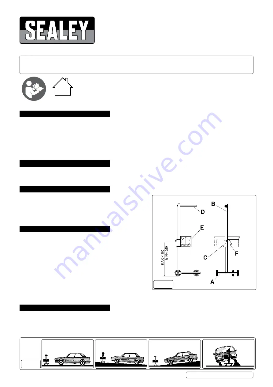
Figure 1
A ......................................................................................BASe
B ................................................................................ColUMn
C ...............................................VeRTICAl SlIdInG SYSTeM
d .....................................................................MIRRoR-VISoR
e .................................................................oPTICAl SYSTeM
F ..................................................................... leVeR SCReW
4.2.
Attach column B to base A using nuts, bolts and washers provided.
Column should be positioned so that optical system mounting
plate on sliding system C is facing the single wheel.
4.3.
Attach mirror-visor d to mounting plate at the top of column B with the
two screws provided (in end of visor).
4.4.
Fit the optical system e to the vertical sliding system C using the two screws and washers provided (fit lever screw F and larger washer
over slotted hole).
5. PREPARATION fOR uSE
5.1.
Working Surface
5.1.1.
Position the vehicle on the designated headlamp aim standing area.
5.1.2.
When positioning the HBS ensure the floor is perfectly even and level.
5.1.3.
If this is not possible the vehicle and HBS must be on the same slope, which must not exceed 0.5º.
5.1.4.
Headlights must not be checked where surface angle exceeds 0.5º (see fig. 2).
fig.1
fig.2
HBS2001 Issue 3 (HF) 14/08/18
Original Language Version
© Jack Sealey limited
Refer to
instructions
Indoor use only
OK
0.5
0
MAX
NO
NO


