


Section 04 ENGINE MANAGEMENT (1503 4-TEC)
Subsection 03 (COMPONENT INSPECTION, REPLACEMENT AND ADJUSTMENT)
NOTE:
This sensor is a dual function device.
When engine is started and it runs at idle speed,
the sensor takes the atmospheric pressure and
stores it in the ECM. Thereafter, it takes the man-
ifold air pressure at operating RPMs.
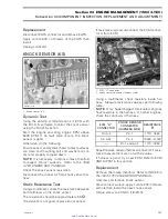
Ensure sensor is correctly installed on intake
manifold. Otherwise, the MAPS could generate a
fault code for an unexpected sensor range at idle
when it reads the atmospheric pressure. Remove
sensor and check for oil or dirt on its end and if
problem persists, check throttle plate condition/
position and the wiring harness. Perform the
following tests.
Voltage Test
Check the voltage output from ECM to the mani-
fold air pressure sensor (MAPS).
Disconnect connector from MAPS and connect a
voltmeter to the terminals of the wiring harness
as per the following table.
CONNECTION
VOLTAGE
Terminal 1 with engine
ground
5 V
Terminal 2 with engine
ground
0 V
Terminal 3 with engine
ground
0 V
Remove and reinstall the safety lanyard to activate
the ECM.
If voltage test is good, replace the MAPS.
If voltage test is not good, check the continuity of
the MAPS circuit.
Resistance Test
Disconnect the ECM connector A on the ECM.
Using a multimeter, check continuity of circuits 12,
28 and 40.
If wiring harness is good, try a new ECM. Refer
to ECM REPLACEMENT procedures elsewhere in
this section.
Otherwise, repair the connectors or replace the
wiring harness between ECM connector and the
MAPS.
Replacement
Disconnect MAPS connector and remove the
MAPS.
Install the new MAPS paying attention to index
its tab into the adaptor notch. Apply Loctite 243
(blue) on screw then torque to 10 N•m (89 lbf•
in
).
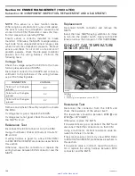
EXHAUST GAS TEMPERATURE
SENSOR (EGTS)
2
F18D2IA
1
TYPICAL
1. Muffler
2. Exhaust gas temperature sensor (EGTS)
Resistance Test
Disconnect the connector from the EGTS and
check the resistance of the sensor itself.
The resistance should be between 2280
and
2740
at 20°C (68°F).
Otherwise, replace the EGTS.
If resistance tests good, reconnect the EGTS and
disconnect the ECM connector A on the ECM.
Using a multimeter, recheck resistance value be-
tween terminals 10 and 26.
If resistance value is correct, try a new ECM. Refer
to ECM REPLACEMENT procedures elsewhere in
this section.
If resistance value is incorrect, repair the connec-
tor or replace the wiring harness between ECM
connector and the EGTS.
126
smr2005-013
www.SeaDooManuals.net


