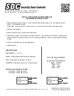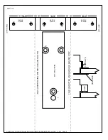
1. Mark and drill as follows: Holes 1, 2 and 3 for #14 sheet metal screws or 1/4 - 20 machine screws.
Hole 4 – 3/8" diameter for wire.
Block strike: Holes 5 and 6 or 12 and 13 for 1/4 - 20 machine screw or #14 sheet metal screw.
2. Tap holes as required.
3. Remove housing cover and mount lock and strike.
4. Attach power leads. Check alignment of bolt and strike. There should be no binding. Leading part of
strike should be 1/8" away from the lock
1/8" is maximum distance
. If this is correct, tighten mounting
screws.
5. Check lock operation for any last adjustments.
6. Install housing.
SPECIFICATIONS
DIMENSIONS: 2" x 2" x 6"
FINISH: US28 standard (dark duranodic optional)
BOLT: 280 series 5/8" diameter 1/2” throw
SOLENOID: 280 series, power lock, continuous duty
280 Series Dual Voltage (Fail Safe):
10.8 Watts – 12VDC @ .9 Amp
10.8 Watts – 24VDC @ .45 Amp
12VDC
CONFIGURATION
.9 AMP
RED
WHT (-)
WHT
BLU
BLK
RED (+)
24VDC
CONFIGURATION
.45 AMP
RED
WHT (-)
WHT
BLU
BLK
RED (+)
Any suggestions or comments to this instruction or
product are welcome. Please contact us through
our website or email [email protected]
P:\INSTALLATION INST\Electric Bolt Locks\TEMP-180-280\INST-280.vsd REV - 09-13 Page 1
INSTALLATION INSTRUCTIONS/TEMPLATE
280 SERIES ELECTRIC LOCKS
801 Avenida Acaso, Camarillo, Ca. 93012 • (805) 494-0622 •
www.sdcsecurity.com • E-mail: [email protected]
BOLT POSITION SENSOR
or
DOOR POSITION SENSOR
SPDT .25 AMP
RED – N.C.
WHT – COM
BLU – N.O.


